Marko's GTD (I think) 40

Hi guys,

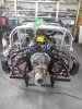
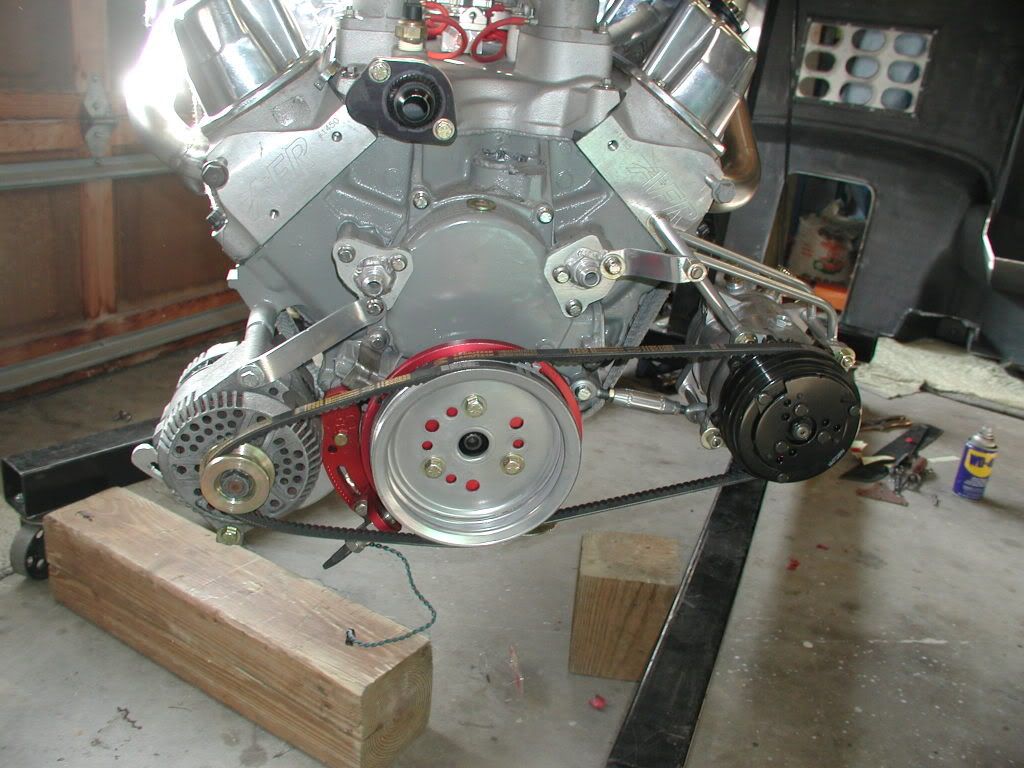
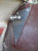
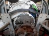
Thanks for that idea Bill. I looked into the electric pumps after your post and that seems like a pretty elegant solution. I later found that the alternator is actually a bigger issue here since the bulkhead is angled towards the rear and the alternator protrudes quite a bit. How did you sort out that situation?

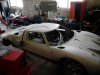
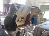
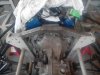
It's been quite a while since my last post and to be honest I haven't done anything. I'm still fiddling with the New Yorker and most of my shop is taken by lathes and mills and saws and welders that I bought. That being the case, the Ford is serving the purpose of a shed for the time being. Something I'm not happy about at all, but since my workshop is also my warehouse, business has to take priority. So sadly, Ford is hard to spot in my garage between all the machinery, shoes, diagnostic devices, chimney pieces and Chrysler bits and bobs.

Meanwhil, I got a CSU 750 cfm blow-thru carb in excellent condition and a complete Holley jet assortment all for 250 pounds (the guy didn't know what he had obviously hehe) and I'm tempted to use the TA45 turbo that's collecting dust on the shelf.

That's all for now. See ya guys.

P.S. If anyone's planning a vacation in Croatia, lemme know, Id be happy to show any of you guys around Zadar.

Cheers,
Marko
 
Here is my first iteration on the alternator/A/C(never plumed the A/C). If you look close you will notice i have a crank trigger in place. It's for the ECU. That adds some length to the crankshaft pulley. The one that is on my car now came from CVF Racing Pulleys.[url=http://www.cvfracing.com/]Billet Aluminum Pulleys and Brackets for Ford, Chevy, Pontiac and Chrysler (Dodge)[/URL] Much nicer and it gives the right turning ratio for the alternator. With all of this I had to shim/spacer the alternator forward to match up with the pulley(s). The A/C sticks a little more forward than the pulleys, even though it is on the back pulley, so you might want to add the mounting of the compressor before you settle on the position of your engine. I believe my compressor is within 1/4" of the frame. I can slip a socket into the pulley(with swivel joint) for fitting onto the crankshaft bolt. Both mounts were fabricated for my particular setup but feel free to build one similar. Can send you more pics if you want them.
Bill

P1010161-12.jpg
 
Hi guys,

It's been a while. I've been really busy and had no time for anything except the work and the kids.

Finally I sold enough machines to clear up my shop and start working on cars. I wanted to sort out the 40 a bit for a photo shoot since I'm trying to sell it but the funniest thing happened. I got hooked again. Now I'm seriously thinking about deleting the ads I've put up for the car. I'm affraid I could experience withdrawal symptoms if it goes.

Anyways. First of off, thanks for your last post Bill. I was fiddling around with the alternator location and it seems that I could fit it in there. Along with the electric water pump and oil filter relocation I should be good regarding clearances.

My newest shop additions, a vertical bandsaw, a Fronius 340 amp welder, a lathe and a mill/drill made me very pleased. I can basically fabricate whatever I want now and I have been doing just that. Did all the engine and tranny mounts, reinforced the cutout I did for the crank pulley, fabricated the steering rack mounts and currently finishing up the rear clip mounts. They were there, but not at a proper angle and welded like crap. Tomorrow I'm making the tranny crossbrace and finishing the rear clip mounts.

That's all for now. I'm in the ford frenzy again so expect more updates soon.

Cheers,
Marko
 

Attachments

  • IMG_20160906_142043.jpg
    IMG_20160906_142043.jpg
    109.2 KB · Views: 323
  • IMG_20160906_142053.jpg
    IMG_20160906_142053.jpg
    93.6 KB · Views: 231
  • IMG_20160906_142103.jpg
    IMG_20160906_142103.jpg
    137.1 KB · Views: 237
  • IMG_20160906_142114.jpg
    IMG_20160906_142114.jpg
    138.6 KB · Views: 249
  • IMG_20160906_142122.jpg
    IMG_20160906_142122.jpg
    154.8 KB · Views: 241
  • IMG_20160831_152004.jpg
    IMG_20160831_152004.jpg
    193.1 KB · Views: 286
  • IMG_20160831_152031.jpg
    IMG_20160831_152031.jpg
    146.7 KB · Views: 282
  • IMG_20160906_150949.jpg
    IMG_20160906_150949.jpg
    127.7 KB · Views: 342
  • IMG_20160906_151107.jpg
    IMG_20160906_151107.jpg
    162.3 KB · Views: 326
  • IMG_20160907_151753.jpg
    IMG_20160907_151753.jpg
    142.1 KB · Views: 280
  • IMG_20160907_151817.jpg
    IMG_20160907_151817.jpg
    136.1 KB · Views: 278
  • IMG_20160907_131042.jpg
    IMG_20160907_131042.jpg
    93.9 KB · Views: 264
  • IMG_20160907_135855.jpg
    IMG_20160907_135855.jpg
    122.3 KB · Views: 261
So I did some more work, as promised hehe. The crossbrace and the rear clip mounts are done. Just gotta drill a few more holes for the crossbrace tomorrow and then on to the rear suspension.

Cheers
Marko
 

Attachments

  • IMG_20160908_104123.jpg
    IMG_20160908_104123.jpg
    106.8 KB · Views: 289
  • IMG_20160908_105720.jpg
    IMG_20160908_105720.jpg
    151.9 KB · Views: 264
  • IMG_20160908_130900.jpg
    IMG_20160908_130900.jpg
    135.9 KB · Views: 261
  • IMG_20160908_145029.jpg
    IMG_20160908_145029.jpg
    126.3 KB · Views: 265
  • IMG_20160908_150530.jpg
    IMG_20160908_150530.jpg
    145.3 KB · Views: 237

Keith

Moderator
Sell it Marko? :stunned:

Noooooo....after all we've been through together? All those sleepless nights & torn fingernails? :cry:

Tell me it was just a bad dream....:squint:
 
Who said anything about selling it? It must be someone with other projects in mind. Me, I know about my 40. I know only about my 40. My 40 is my only mission. I know nothing else. How did I get here anyway? And why aren't I at my workshop?
 

Keith

Moderator
Well Marko, there was this:

" I wanted to sort out the 40 a bit for a photo shoot since I'm trying to sell it but the funniest thing happened. I got hooked again. Now I'm seriously thinking about deleting the ads I've put up for the car. I'm affraid I could experience withdrawal symptoms if it goes."

So naturally I got worried... :drunk:
 
God forbid. I mustve been outta my mind when I wrote that :) But seriously, I made room in my shop and got some more time on my hands now so I think Ill keep putting it together and cancel the ads. I was in a period a while back where I didnt think I could start assembling it anytime soon.
 
Your pictures don't look like a GTD frame or suspension bits. The body might be GTD. Maybe someone else can identify the heritage.
 
Yup I know mate. The guys identified it as a Hi Tech Welding kit, an English company from the 80s. Changed six or seven owners and never been put together. This burden that has befallen me, to end this cursed spree, has almost became too heavy to carry on my tired shoulders, but "nay!", I say, you shall not change hands unfinished yet again, you forsaken chariot, and I shall have horses pull your frame down the muddy street if need be before I accept treasures for you!
 

Keith

Moderator
Yup I know mate. The guys identified it as a Hi Tech Welding kit, an English company from the 80s. Changed six or seven owners and never been put together. This burden that has befallen me, to end this cursed spree, has almost became too heavy to carry on my tired shoulders, but "nay!", I say, you shall not change hands unfinished yet again, you forsaken chariot, and I shall have horses pull your frame down the muddy street if need be before I accept treasures for you!


:lol:

Well put mate!
 
So today I finished the crossbrace and then went on to sorting out the rear suspension. Everything is level and at proper heights and none of the movable parts rub or hit against anything but havent had enought time to finish the RHS today. Will continue on monday. So far it looks fine to me but if anyone spots something fishy about my setup please tell me. Id rather know about now than in the middle of a 150mph corner :)

Cheers
Marko
 

Attachments

  • IMG_20160909_153540.jpg
    IMG_20160909_153540.jpg
    80 KB · Views: 246
  • IMG_20160909_153518.jpg
    IMG_20160909_153518.jpg
    136.4 KB · Views: 245
  • IMG_20160909_153508.jpg
    IMG_20160909_153508.jpg
    122.1 KB · Views: 237
  • IMG_20160909_153450.jpg
    IMG_20160909_153450.jpg
    152.8 KB · Views: 251
  • IMG_20160909_153317.jpg
    IMG_20160909_153317.jpg
    154.3 KB · Views: 244
  • IMG_20160909_153248.jpg
    IMG_20160909_153248.jpg
    88.8 KB · Views: 242
  • IMG_20160909_150303.jpg
    IMG_20160909_150303.jpg
    113.4 KB · Views: 261
  • IMG_20160909_153551.jpg
    IMG_20160909_153551.jpg
    182.6 KB · Views: 279
  • IMG_20160909_103258.jpg
    IMG_20160909_103258.jpg
    83.8 KB · Views: 210
  • IMG_20160909_103244.jpg
    IMG_20160909_103244.jpg
    79.6 KB · Views: 236
Hi guys

I was working on few things for the last couple of days. First of all, I almost finished my sheet metal bender for bending sheet metal :D Secondly, I sold my Fronius Synergic. The guy gave me an offer I couldn't refuse. In cash. So I'm stuck with some crappy 170 amp mig for the time being until the Fronius TPS 330 arrives from the UK. 500 quid, a bargain :) I also got some 200 kg of regular and a few kg of stainless steel so I'm good for a while.

Now on to the car. I was working on the rear suspension for the last few days, trying to get the LHS in line and making spacers. I'm almost done with them. For testing purpuses I made them out of regular steel tube but next week after I finish setting everything up I will make tapered spacers out of stainless steel.

I finished the rear sway bar too. Drilled and welded plates at each ends with five different holes so that it can be adjusted for stiffness. I also made brackets and welded them on the crossbrace. One thing has been bothering me lately and that is that I will have no room for the exhaust. I might have to change the crossbrace design later on. TBH, I didn't do a very good job thinking that design through.

Today I was working on the bulkhead bulge. The reinforcement I fab'ed up on the bottom of the bulkhead was very much appealing to me so I decided to replicate the same one on top where I had to cut out the horizontal tube below the rear window to fit the distributor in there. I then connected both with more square tube. I now refer to that part of my car as "THE CAGE".

That's all for now. Back with more news in a few days.

Cheers,
Marko
 

Attachments

  • IMG_20160912_115519.jpg
    IMG_20160912_115519.jpg
    81.5 KB · Views: 246
  • IMG_20160915_103802.jpg
    IMG_20160915_103802.jpg
    74.4 KB · Views: 235
  • IMG_20160915_121133.jpg
    IMG_20160915_121133.jpg
    97.9 KB · Views: 233
  • IMG_20160915_121844.jpg
    IMG_20160915_121844.jpg
    191.1 KB · Views: 275
  • IMG_20160915_121854.jpg
    IMG_20160915_121854.jpg
    113.8 KB · Views: 249
  • IMG_20160915_145437.jpg
    IMG_20160915_145437.jpg
    104.5 KB · Views: 227
  • IMG_20160915_145443.jpg
    IMG_20160915_145443.jpg
    96.4 KB · Views: 242
  • IMG_20160915_145455.jpg
    IMG_20160915_145455.jpg
    104.9 KB · Views: 245
  • IMG_20160915_145501.jpg
    IMG_20160915_145501.jpg
    113.5 KB · Views: 250
  • IMG_20160914_134617.jpg
    IMG_20160914_134617.jpg
    75.3 KB · Views: 220
  • IMG_20160915_083526.jpg
    IMG_20160915_083526.jpg
    103.2 KB · Views: 240

Ian Anderson

Lifetime Supporter
How close to the top of the box is that rear crossmember?
Is just above it then exhaust should fit.they are always tight!

Could you move your roll bar to fit into n rear of the cross member instead of on top?

And on that cross member, cut it off on both sides, weld on plates and bolt it in place so it is removable, you will thank me later when you have to fit the engine and box to trial fit, tweak, adjust and fit again

Ian
 
Hi Ian,

Thanks for the advice. Some of it I already have covered. The roll bar is in the rear of the crossbrace, only the brackets are held on the upper side of the brace but at the points where there is a slope in the brace. The sway bar is parallel with the upper side of the crossbrace. Also, the crossbrace is already cut at the ends and so is the horseshoe. The crossbrace's outer width is the same as the upper part of the horseshoe's inner width so it slides right in and it's held in place with two bolts on each side.

There is some room between the crossmember and the box, how much I don't really know by heart. If I would have to guess I would say some 2 or 3 inches. It's not a huge job though, even if I have to redo it, but I would prefer to continue working on other areas rather than cut something twice.

Cheers,
Marko
 

Terry Oxandale

Skinny Man
Perhaps this was covered already and I missed it, but I have a question about how the lower trailing arm clevis at the rear upright, where it is attached to the threaded rod being used to hold it all together (see attachment, area within the red circle). Is this spot welded to the threaded rod, or is this just a mock-up piece?
 

Attachments

  • ScreenShot1730.jpg
    ScreenShot1730.jpg
    66.9 KB · Views: 275
Last edited:
Hi Terry

Thanks for pointing that out. It has been tack welded from the thread side of it. The side you marked in that photo has had the threaded rod pass through the hole in the U bracket and then the rod has been flatned with the press as to produce a firm grip with the bracket and is now level with the bracket base. I will do the final welds prior to final assembly. I also have to shorten the upper thread and paint the clevis pins.

Cheers
Marko
 

Terry Oxandale

Skinny Man
Thanks Marko. May I offer an alternative? I fabricated my clevises much like what it appears you have done. I chose rectangular tubing that was cut to make the clevis as a single piece, but more importantly, the hole for the threaded rod (in your case) is instead a hole for a bolt to pass through. The result is a grade 8 bolt, with full strength at the head, which is used to clamp the assembly together with the nut on the other side of the upright (as you've done). It worked out that the shank of this long bolt is un-threaded, so that only the end that sticks out is threaded.

The only reason I offer this suggestion is my concern that given the stress placed on the weld and peen when you torque the nut, the long length of threaded rod, and the result of possible failure of the weld under that stress. With the unmodified bolt, you have the full strength of the bolt, which for the same OD of the fastener (threaded rod vs bolt) will most likely be stronger. Attached is what I did. We can get high strength threaded rod here, but the bolt would appear to be much simpler and stronger.
 

Attachments

  • ScreenShot1466.jpg
    ScreenShot1466.jpg
    23.4 KB · Views: 275
Last edited:
Hi

That's a very good point Terry. The clevis pins are one of the first parts I had done for the Ford, so I was still getting into the whole "think it through" thing. It does make perfect sense what you're saying and I will gladly take your advice. I do have a question however. The pin has to have an angle to it. If you used a rectangular pipe it has 90 deg angles on it, as I see you did by your photo. If that's the case the bolt itself has to be tilted at an angle as to acommodate for the angle between the clevis pin - trailing arm pickup point line and a line in the upright parallel to the centerline of the car. Or did you simply bend the tube you used for the clevis to an appropriate angle?

After completing the sway bar I wanted to test fit everything. I lowered the engine and found that one of the original Ford aluminium mounts needs to be redone. The cage is getting in the way of lowering the engine in. I did eventually get it in but it's definitely not convenient so I will have to fabricate another one. Looking at the engine bay from the cockpit a phrase "the beast has been caged" came to mind :)

After the engine was in I mounted the crossmember and sway bar and hinged the rear clip. By the way I'm not happy with the way the clip is mounted so I'll cut those brackets off and make something completly different. Still thinking that part through though. Anyways, there was some cutting and grinding on the clip to make it close properly but in the end it's fine. I forgot what joy it is working with fiberglass. After realizing every single surface in my shop has a think layer of that horrid thing on it I swore I'll make a trolley for the Ford and take it outside every time there's fiberglass work to be done. Or get someone else do it. I'm horrible at it anyway.

I have a question about the clip though. The carb sticks out quite a bit, and at an angle. I know the engine is level and the clip only has half an inch to go on the RHS (too high an oil cap). I also know that the trumpets on the webers usually stick out, but this seems kinda exsessive. What do you guys think?

Last night I started work on the stainless steel spacers. The taper is 15 deg. First one was pretty bad so I discarded it. Second one was usable after some more work on it and third and fourth seemed pretty decent considering this is my first serious use of the lathe and first time working with SS. So I was pretty pleased with my self around 1 AM today. So much so that I even cleaned some rat poo that I found in one of the trailing arms pickup points before installing the spacers so that it doesn't ruin the photo.

Cheers,
Marko
 

Attachments

  • IMG_20160916_122929.jpg
    IMG_20160916_122929.jpg
    95.6 KB · Views: 187
  • IMG_20160916_123636.jpg
    IMG_20160916_123636.jpg
    125.8 KB · Views: 255
  • IMG_20160916_123757.jpg
    IMG_20160916_123757.jpg
    85.5 KB · Views: 213
  • IMG_20160916_144317.jpg
    IMG_20160916_144317.jpg
    92.4 KB · Views: 216
  • IMG_20160916_144417.jpg
    IMG_20160916_144417.jpg
    88.7 KB · Views: 196
  • IMG_20160916_144447.jpg
    IMG_20160916_144447.jpg
    110.3 KB · Views: 211
  • IMG_20160916_144509.jpg
    IMG_20160916_144509.jpg
    100.7 KB · Views: 201
  • IMG_20160917_230946.jpg
    IMG_20160917_230946.jpg
    80.4 KB · Views: 166
  • IMG_20160917_231636.jpg
    IMG_20160917_231636.jpg
    93.9 KB · Views: 184
  • IMG_20160918_000228.jpg
    IMG_20160918_000228.jpg
    71.6 KB · Views: 171
  • IMG_20160918_000237.jpg
    IMG_20160918_000237.jpg
    47.4 KB · Views: 187
  • IMG_20160918_001131.jpg
    IMG_20160918_001131.jpg
    123.2 KB · Views: 171
  • IMG_20160916_131545.jpg
    IMG_20160916_131545.jpg
    68.5 KB · Views: 164
Back
Top