
Thanks Cam. Anything to keep the wind noises from being an issue.

- Forums
- GT40 Replica Manufacturers' Corner
- RCR Forum - RCR40/SLC/917/Superlite Aero
- The SLC Clubhouse
You are using an out of date browser. It may not display this or other websites correctly.
You should upgrade or use an alternative browser.
You should upgrade or use an alternative browser.
Mark's GT-R Build
- Thread starter mksetter
- Start date
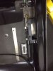
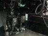
With the interior tub in place, but not screwed down, I can now work on finishing the details in the interior. I am at a standstill in the wiring, waiting for some items ordered from Infinitybox. One of the areas I wanted an addition was in the area of fuel pump shut off. I got a G force switch from a Mustang GT that will serve as the first line of defense in the event of an accident getting the fuel pumps to shut off. The second comes in the form of a manual fuel pump shut off switch.
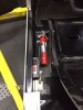
I mounted both of these switches near the driver side door sill, adjacent to the parking brake level. The reason for this is every time I exit my sports cars of any sort, I put my left hand on the driver door sill in getting out of the car. In the event of an emergency, I would still be using that location as a hand rest. Makes sense to put the fuel shut off switch there.
I mounted the fire extinguisher in that same area, for easy access after I get out of the car.
Sorry about the photos changing orientation. I don't know why it does that or how to fix it.
Attachments
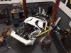
Now that I have the interior tub in place, I am mocking up the complete interior to fine tune the fit of the tub and to get all of the parts ready for powder coating, upholstery or whatever covering they will need.
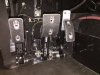
With the seats in their final position, the pedals in their position and the tub level of the flooring set, I really had a hard time with the height and angle of the accelerator pedal. I have a layer of Luxury Liner Pro under the tub, but also added a layer on top of the tub in the foot well of the driver and passenger area, in part to reduce the relative height of the accelerator pedal. It was still too high, so a modification was in order.
I wanted to use the supplied foot pedal, but it needed to be lower and at the angle of my foot in a driving position. With all of the flooring in place, I measured the distance from the heel of my shoe to the ball of my shoe and set the pedal height as that distance off the floor height. Tried it out, and that is the right position. I will have the exposed aluminum powder coated with the other interior support pieces.
I added the foot rest that I previously made, so the driver side foot box is complete.
Attachments
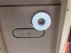
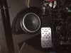
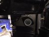
With the passenger seat in place, my plan was to have the subwoofer behind the passenger seat. I measured the space previously, but have never had the subwoofer in place.
It is a tight fit, but I plan to leave the back of the seats as painted fiberglass, so the seat should not absorb too much of the bass output.
It is a tight fit, but I plan to leave the back of the seats as painted fiberglass, so the seat should not absorb too much of the bass output.
Attachments
I am working on a few things at the same time, basically putting off the wiring as much as I can. I love the fabrication, hate the wiring.
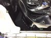
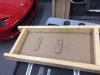
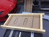
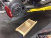
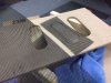
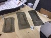
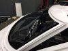
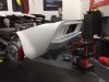
I really like the look of the contoured wire mesh grills on the Ford GT and on my Ferrari. Not the a flat mesh grill looks bad, but a 3D look to the grill is better, at least for me, and it is worth a little effort to get it.
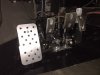
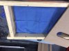
I looked up on YouTube how to make 3D audio grills and basically used the same ideas. I made up a forming box and used MFD (?) board for the top and the bottom, and also for the forms. The forms were made from a cardboard outline of the rear body openings. The edges of the male portions of the from need to be beveled so as not to merely sheer cut the wire mesh. Double sided tape was used to hold all of the pieces in position. With the male form in place, then the wire mesh grill, then the female outline, then a cloth towel to keep from scratching the power coating on the wire mesh. then the top of the forming box, all of which I put under my hoist to place the load on the system.
The grills formed just as I wanted. (Sorry about the picture alignment.)
I really like the look of the contoured wire mesh grills on the Ford GT and on my Ferrari. Not the a flat mesh grill looks bad, but a 3D look to the grill is better, at least for me, and it is worth a little effort to get it.
I looked up on YouTube how to make 3D audio grills and basically used the same ideas. I made up a forming box and used MFD (?) board for the top and the bottom, and also for the forms. The forms were made from a cardboard outline of the rear body openings. The edges of the male portions of the from need to be beveled so as not to merely sheer cut the wire mesh. Double sided tape was used to hold all of the pieces in position. With the male form in place, then the wire mesh grill, then the female outline, then a cloth towel to keep from scratching the power coating on the wire mesh. then the top of the forming box, all of which I put under my hoist to place the load on the system.
The grills formed just as I wanted. (Sorry about the picture alignment.)
Attachments
-
 IMG_5146.JPG40 KB · Views: 321
 -
 IMG_5145.JPG41.7 KB · Views: 338
 -
 IMG_5147.JPG79.5 KB · Views: 305
 -
 IMG_5148.JPG40.4 KB · Views: 348
 -
 IMG_5150.JPG47.7 KB · Views: 278
 -
 IMG_5151.JPG43.7 KB · Views: 298
 -
 IMG_5152.JPG43.2 KB · Views: 312
 -
 IMG_5153.JPG49.6 KB · Views: 333
 -
 IMG_5155.JPG84.9 KB · Views: 322
 -
 IMG_5157.JPG27.2 KB · Views: 340
 -
 IMG_5158.JPG24.9 KB · Views: 338
 -
 IMG_5159.JPG54.3 KB · Views: 317
 -
 IMG_5160.JPG55.8 KB · Views: 333
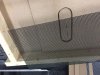
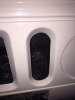
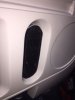
After the small grills were run, I was confident the systems worked, so I then repeated the process for the larger rear grill opening. They fit great, but I will wait on installing them until after the paint work is finished.
Attachments
Mark, love the look of the contoured wire mesh grills. Thanks for posting all the details you went through making them. Awesome work!
I finished the wiring on the fuel pumps and have just a few more circuits to go before starting the motor.
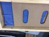
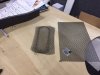
I made up some door panels to fill in the openings from the factory. I used fiberglass pieces left over from trimming the interior tub. After getting the size and shape worked out, I plan to use exposed black hex head bolts as a design theme throughout the interior. In this case, I epoxied the nuts to the inside of the door panel to make install and removal easier.
For the doors, I next will coat the inner raw fiberglass with Second Skin Audio Spectrum, then add a layer of Luxury Liner Pro to all of the inner surfaces.
When the interior finished surface materials are added, I will have these panels covered in a different material for contrast.
Attachments
Thanks Kurtiss. You are going to love building this thing!
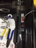
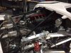
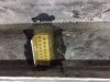
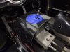
Mark - in your second photo there is a canton tank on your right frame rail. Are you using that as your overflow catch can or as an expansion tank?
Hi Cam:
The Canton tank is under pressure as the expansion tank, with the overflow tank next to it.
The Canton tank is under pressure as the expansion tank, with the overflow tank next to it.
I am working on completing a full mock up of the interior, with every item fully installed. When I have it all together, I plan to start the car, "go kart" it around the parking lot, then install the body. That being done, I will then take it all apart and start working on getting final finishes done.
With that as the plan, I installed the foot well audio speakers with final wiring.
With that as the plan, I installed the foot well audio speakers with final wiring.
Attachments
I spent most of the day trying to get the dashboard in position. When I first put the dash in place, I was trying to minimize the cuts made into the fiber glass. I measured everything and got a really precise fit.
It was a total waste of time.
Putting the dash in without the roll bar in place is simple. It is another thing to get it around the roll bar and body work. Thankfully Fran previously sent out pictures of the interior "A" pillar trim pieces so it allows for some freedom in adjusting the dash ends to get it seated. I will send photos of what I had to trim to get it seated.
I am making "mounting posts" that will allow me to screw the dash in place at the proper height to match the cowling at the base of the windshield. I am amazed at how precise Fran has made these parts. The dash needs 3.25 inch posts at each end and 4.75 inch posts between the defrost depressions in the top of the dash. Perfectly symmetrical on each side. Not and 1/8th off.
Attachments
You will be driving it before you know it, keep up the good work, at this point it looks like you will finish before me!!!
H
H
The only reason I will finish before you is because you will be adding a bunch of really awesome stuff that no one else can even think of, let alone do. I still don't have the wiring finished. Waiting to find out from Infinity how to connect the Dominator fan control wiring through the Mastercell, then out to the front Powercell. They are working on it (I think.)
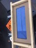
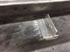
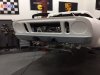
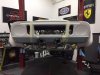
Today I want to mount the rear bumper that I previously modified to have separate dual exhaust exits and have a low center mounted third brake light. In thinking about this, it is really a challenge. First of all, it has to be perfect. An eighth of an inch off will look like a mile off. Second, since you do not want to see the bracket when you are finished, you really can't see the bracket while you are working on it. The bumper amounts to a box with one wall open facing the body of the car. Third, most of the surfaces involved are very difficult to get accurate measurements on because they are progressive curved surfaces, so the degree of curve depends on where you are on the body surface.
My solution was to develop an adjustable mounting bracket, adjustable both vertically and horizontally. Once the holes are drilled in the body, if there is any degree of asymmetry or error, the mounting bracket would allow for corrections.
My solution was to develop an adjustable mounting bracket, adjustable both vertically and horizontally. Once the holes are drilled in the body, if there is any degree of asymmetry or error, the mounting bracket would allow for corrections.
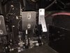
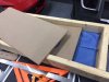
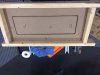
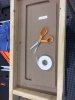
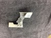
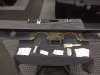
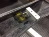
The first piece needed to be the attachment plate that would be glassed to the inside of the bumper. Measurements showed the best place to attach the bumper, avoiding other components inside the rear body work and avoiding a flat area that would allow the bumper to "wobble", was 11 inches outside of the exhaust outlet.
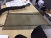
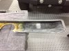
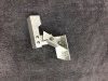
I roughened up the interior of the bumper and perforated a bracket plate. I made the bracket using two nuts and bolts for all of the attachments except the one location allowing the bracket to be adjustable. For the adjustable attachment point, I made the holes ovals to allow vertical and horizontal movements.
The last two photos show the "dry run" of placing the brackets before attaching to the bumper.
Looks great so far.
Attachments
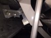
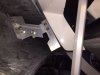
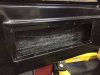
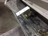
Knowing the bracket will work, I fiber glassed the mounting bracket to the inside of the bumper. After hardening, I attached the remainder of each bracket.
I positioned the bumper where I wanted it and taped it everywhere I could. After some adjustment of the brackets, I marked the holes, drilled and bolted the bumper in place, with fender washers spreading the load on the inside of the rear body work.
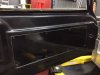
Once in place, no other adjustments needed, so I drilled a second hole beside the adjustable attachment point to finalize the bumper position. You can see the location of the third brake light in the mounted bumper.
Looks great!
Next Up - The Console
I positioned the bumper where I wanted it and taped it everywhere I could. After some adjustment of the brackets, I marked the holes, drilled and bolted the bumper in place, with fender washers spreading the load on the inside of the rear body work.
Once in place, no other adjustments needed, so I drilled a second hole beside the adjustable attachment point to finalize the bumper position. You can see the location of the third brake light in the mounted bumper.
Looks great!
Next Up - The Console
Attachments
A big "THANKS" goes out to Ron McCall for spending the time and the energy to have the bumper developed and made available to us. For me, in building a street car, the bumper is a great addition to the finished look of the car.
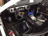
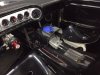
I think the Audi shifter will be really a nice improvement to the driving experience of the GT-R, but with the gas tank in the center console (which is the right place for it.) the shifter is difficult to mount and makes for a real challenge to design a console to hide it. Even master builder Allan said in a video that this challenged his talents.
To avoid starting from scratch in making a new console, I cut the top half of the RCR supplied console in the tub right off and saved the removed piece to serve as the basis for the new console. The first piece had to center on the shifter. It is not possible to have the Audi gated faceplate on top of the fiberglass because the screws to secure the faceplate would be blocked. You can have the faceplate below the level of the fiberglass, but then there is the issue of filling in the "gap." The other option is to have the fiberglass on top of the faceplate, which appears to be the most common choice and is the choice I have elected. I want to make this section of the console as small as possible to improve the viewing of the audio screen that will be mounted in the vertical portion forward of the shifter.
I will refine the opening for the faceplate after the console is complete. I plan to have the entire console covered, probably in leather.
Attachments
Similar threads
- Replies
- 4
- Views
- 332
- Replies
- 0
- Views
- 203