Stephan E.
Supporter

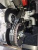
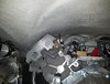
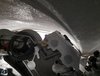
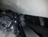
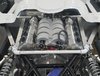
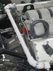
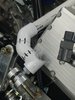
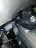
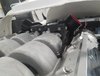
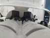
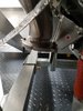
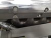
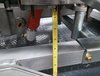
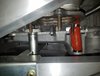
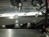
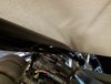
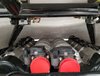
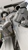
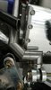
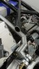
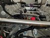
Joel was over today and helped me to set the body on to check if the rear shell will clear the engine. We set preliminary ride height to clear the wheels. We had to keep our fingers crossed when we lowered the rear. AND IT DOES FIT!
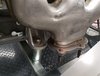
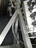
Now I have to figure out the exhaust and rear cross brace design...
Thanks Joel,
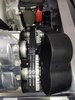
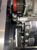
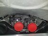
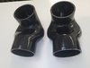
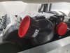
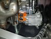
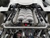
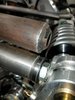
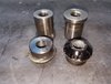
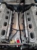
I think these adapters could be an option to various SLC turbo and supercharger applications or even standard LS or any other engine with forward facing throttle bodies. They are good for positive and negative pressure. If someone is not into cutting body, firewall, structural components or simply prefers to have the air filter not in the back or does not like the rear scoop they could create an alternative. Available up to 7 inches openings in hard plastic, silicone and rubber depending on who manufactures them.