Ohio MDA

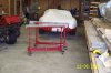
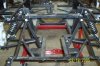
O.K. so its not a photo of the car. I'm building a windscreen closet to protect them (I've got two boys ages 4 and 6) from breakage, and I've been wanting to get the chassis stands finished before unlaoding the car from the trailer. Closet's half done, and stands are now ready. They turned out better than I thought they would, so I thought I'd share the results with a shot of them. Next time you see them, the chasis will be on them.
Jim
 

Attachments

  • 53475-standsweb.jpg
    53475-standsweb.jpg
    53 KB · Views: 727

Howard Jones

Supporter
Jim. Us GTD folkes await you pictures.Please post a lot.I believe that just about all the stuff I am fixing on my GTD, suspention pieces, mounting points for engine and gearbox, and stuff like that are already part of the MDA's. Close ups! If you please.
 
Hey Howard,
as soon as I get tht body off, I'll shoot some frame photos on the site. If you need any specific detailed frame shot close up, I'll email them dirctly to you as I don't want to take up space on the forum. We'll give Ron a break on that one. There must be quite a few unfinished GTD's out there. Didn't they go belly up around 10 years ago, or was it more recently.
 

Howard Jones

Supporter
Jim, My car is "done" as you car see from my pictures. I am interested in the area under the gearbox. The width of the GTD frame in this area limmits how low you can mount the motor in the car.

Also any and all suspension pickup points, along with pictures of the A-arms would be good also. The location of the rear upper single link inboard mount, from the upright to the chassis, is also an area on a GTD that needs attention. Pictures of this area would be very cool.

The mounting area for the steering rack is another area that can be improved on in a GTD and would be interesting.

As you can tell from my interest, these are the things that could have been improved on with the GTD design. I was wondering what Mark did in these areas as compaired to my solutions. Some are done and some are on the drawing board.

Thanks, don't hurry, when you have time.

Howard Jones
 
Jim, there are a bunch of us like Howard out there. We know most of the competetion guys in the UK have seriously re-worked the rear suspension points on the car and as Howard suggests the steering in regards to bump steer and Ackerman. Although I do not plan on modifying my car until it has been on the road a while, photos will be appreciated.

Brian
 
As well as continuing to supply the proven GTD Chassis - Roy also manufactures all suspension/upright parts, from standard, to improved fully adjustable items. (not wishing to hijack thread - just passing detail) /ubbthreads/images/graemlins/cool.gif
 

Attachments

  • 54320-RoySuspRearandFront.JPG
    54320-RoySuspRearandFront.JPG
    42.8 KB · Views: 653
I need to get a few friends over to help set the car up on the new stands. Is there a specific angle you'd like the photo's taken from. What about dimensions, I can get you those too, but need to know exactly what you're looking for. Oh yea, I'm sorry to say you U.K. guys will get dimensions in the dreaded imperial system instead of the metric system. Hey, didn't the U.K. create the imperial system anyway. What the H*ll happened there anyway. I'll try and get some pics this weekend or by middle of next week. Just let me know if you'd like those dimensions. (I'll try and find a metric tape measure)
 

Howard Jones

Supporter
That's just about it. I can see that the MDA has allowed a lot more room under the rear of the gearbox (R21) and it apears to have raised the pickup point for the single top link on rear. This to reduce bump camber change. The front looks like what I have already drawn and is in front of me as I write this. The rod ends will not only allow good adjustment of camber but also allow for plenty of caster adjustment. Both of these are at the center of the GTD front suspension problems.

Nice job Mark!! Just what the old girl needed!
 
Hi guys

In my humble opinion I would expect to see a strong chassis member between the inner lower suspension pivot points, under the horse collar (Bellhousing) this area of the chassis takes a lot of strain.

Chris.…
 
[ QUOTE ]
Hi guys

In my humble opinion I would expect to see a strong chassis member between the inner lower suspension pivot points, under the horse collar (Bellhousing) this area of the chassis takes a lot of strain.

Chris.…

[/ QUOTE ]

Wouldn't it be possible to make a 'bolt-in' member ?
 
Hi Julian

A bolt in member may be a possible solution but remember it will be taking compressive and tensile loads.

Only trying to help
Regards
Chris.
 

Robert Logan

Defunct Manufactuer - Old RF Company
Julian,

I MUST concur with Chris on this one. I also feel that the rear chassis needs some sort of stiffening particularly as the engine / box is not a structural member in this car. I have not examined a MDA chassis up close and I am wary about commenting on NON COMPLETED stuff.

In Australia we have to take our cars through a "Torsional and Beam" set of tests. The torsional test is conducted by SECURING the chassis at three of the points of wheel centers (lets say suspension pick up) while the fourth point has a load applied to it and an allowable deflection is permitted for a given load. The allowable loads and deflections are dependant on the engine size and interestingly enough this is in CYLINDERS (ie. 4 - 6 - 8 cylinder and in my opinion should be HP and Torque related).

The beam test is where the same points are used and weights corrosponding to the seating capacity are added and the deflection of the chassis downwards to the floor is measured. A factor of safety (FOS) is used in the weights that have to be used in both tests ie. a two seater like the GT40 has the weight of FOUR people to be added for the beam test. Again allowable deflections are given for the type of car. These tests are both difficult and expensive and there are some cars (not GT40's) that have failed to reach the numbers required here in Australia. Cobra's are particularly difficult to get through these tests as many manufacturers insist on using the original "ladder" type chassis. Mistake!

I must admit that I am very suprised that the SVA does not include such a BASIC safety test (please correct me if I am wrong here).

The best way to stiffen up chassis is with WELDED sections and bolted sections are never as good but that does not say that they are at least adequate. The torsional test is realy the only way to satisfactorly test.

As a final point I must say that our chassis far exceeds the test requirements as all race cars would and it could easily be that the MDA chassis passes torsional tests and I believe it would with the brace that Chris discussed in this thread.

Best wishes,

Robert
 
Robert,

do you have a similar picture of this area for your chassis ?
I can understand you may not wish to post it here incase this turns into a mud-slinging match, but it would be interesting from a potential purchasers point of view to see just how similar (or not) the chassis are in this area.

Regards,
John.
 
I believe you can see it on Dan Weilacher's RF - check
the Builder's Forum - Roaring Forties #091.

Here's a direct link - you can barely make out the welded in crossmember.

Ian
 
Back
Top