GTD40 suspension upgrade

Time for some suspension upgrade.

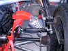
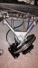
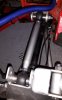
I have the standard GTD40 non adjustable suspension with bushings.
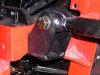
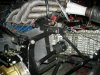
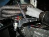
Front the Granada MKII uprights and rear the GTD steel uprights with MKIII hubs.

- converting to adjustable suspension with rose joints: Here I wanted to use the Southern GT solution for front and rear. I think this is the easiest solution and a good one?? But expensive....

- Rear suspension top link problem: I have found on the forum that there is a problem with the rear geometry due to the big change of the camber during movement. I can tell that I experienced this a few times, scary:stunned:....... So to solve this, one could lower the position of the upper arm connection on top of the upright? This is easier than changing the position on the upper chassis connection. Can someone inform how much and where to change before inventing the wheel again and start measuring/calculating...Would be nice...

So this is a good start..thanks in advance:thumbsup:
 

Mike Pass

Supporter
Hi Curt,
I will look up a pic of a rear upper arm pick up point modification using a bracket. I also have a set of used front rose jointed wishbones lying around.
Cheers
Mike
 

Mike Pass

Supporter
Here are the pics of the modifications to the upper rear link chassis mount. As the pick up point is further out from the chassis and raised up this reduces the rate at which the rear camber increases as the suspension moves upwards.
Cheers
Mike
 

Attachments

  • GTD rear susp mod.jpg
    GTD rear susp mod.jpg
    128.8 KB · Views: 784
  • GTD rear susp mod2.jpg
    GTD rear susp mod2.jpg
    100.7 KB · Views: 731

Howard Jones

Supporter
Ya, That's mine. The reason I used a bracket was I didn't want to weld on the chassis. Welding a new set of mount ears would achieve the same results.

I didn't try changing the pickup point on the upright so I can't speak to that. All of this was carefully documented by Derek Bell, yes the real guy, on his web page that used to on line. I haven't been able to fine it however for several years. Does anybody have his paper on the GTD suspension fixes?
 
Mike,
Thanks!!, would be interesting, those wishbones? Were did they come from and in what condition are they?

Howard,Mike
I saw these photo's in some threat somewhere:idea:... Yes this is the way I could go.
Disadvantage is that I also need to make an other "cross-link" plate above the gearbox to relocate the sway bar to a higher position.
That's why I was thinking on lowering the upright connection. Just making 2 holes. And perhaps also lowering the other side of the trailing arm? Someone was here was using this, but did not save the thread:shout:

Didn’t know that Derek Bell "the man himself" was getting involved with the GTD. Would be nice to read about his advice.

But do you also have dimensions of the X-Y transition of the mounting point?

THX Curt
 
Not certain of this , but for what it is worth - I believe Derek Bell was driving a much modified GTD Lola T70 and that is were the ideas for the suspension mods came from. I think he also inspired the Renault Tranny mods.
 
Curt,
I did the suspension upgrades to mine after reading all the threads on the forum. I layed mine out on auto cad and have all the dimentions if you want them.
Bob
 

Attachments

  • DSCN1034.jpg
    DSCN1034.jpg
    246.2 KB · Views: 707
  • DSCN1047.jpg
    DSCN1047.jpg
    215.1 KB · Views: 653
@Mike, I've sent a mail to your private E-mail address.. Thanks for the support.


@ Bob, That would be great, Will help me a lot. I've sent a PM.:thumbsup:
 

Malcolm

Supporter
Sorry to pop the bubble, but the Derek Bell who had the GTD Lola T70 and was responsible for Quaife making the UN1 gear box kits is NOT the Derek Bell of Le Mans and F1 fame. Just a clever bloke who made and drove a rather fast car with the same name. He did get John Surtees to drive his T70 replica who complimented it highly though.

To lower the rear arms on the upright end on a GTD, you need to drill a new hole as low as possible on the same flat surface that the existing hole is. To get the equal on both sides of the same upright, remove the existing arm, make a plate that bolt to the existing hole, drill a pilot hole where you want it to end up and then use that for both sides of the upright and then repeat on the other side. Once all four pilot holes are drilled open them up to the correct diameter for the suspension bolt. If wanted you can put a spacer inside the upright to stop the tightening of the bolt squeezing the upright out of shape, I didn't and have never suffered for it though. Job should take about an hour if taking care. It isn't a tricky one to do!

To really get the back end of a GTD under full control you need to lower the engine and the Southern GT rear end swap is well worth it. If you want front adjustable suspension arms then the Southern GT ones are also the simplest way to achieve a good result.
 
Malcolm,

Thanks to clarify. I checked on the car and this will be 35mm down and 15mm outwards where the new upper pivot point will come.

But I do not need to lower pivot point on other end of the upper control arm with the same amount?

Greetz Curt
 

Terry Oxandale

Skinny Man
No. The purpose of the modification is to decrease the angle of the upper control arm to a more horizontal configuration. Thus you can either 1) lower the outer pivot point, or raise the inner pivot point. Changing them both nets zero improvement (sans the additional benefit of this mod in lengthening the upper arm by 15mm per your last post).
 
Hello Terry,

Sorry that was not what I wanted to ask.
What is meant was the other longer arm I think its called trailing arm in English? The ones connected to the firewall near the seats?

Hope this is clearer...:thumbsup:
Gr Curt
 

Terry Oxandale

Skinny Man
Some others may be more knowledgeable about the trailing arms. IMHO, this is also not necessary, though because it is attached with the same bolt as the lateral link, it is most convenient. It does impact squat on acceleration, as well as slight changes in rear caster. lowering the rear of the upper trailing arm should increase the anti-squat, but the primary improvement, and perhaps the only thing you'll actually notice is the re-positioning of the upper lateral link as described above in previous posts.
 
Last edited:

Howard Jones

Supporter
Thanks for the clarification Malcolm. I have head it both ways over the years. I'll call him Mr. D Bell from now on. I did nearly all of his mods to my car. They really transformed it.
 
After some winter months some time for a update.

- Front suspension: Here I went for the Southern GT solution. I had to cut some material away from the lower arm to avoid contact with the disc. Also I could experience the difference in longitudinal position of the the left and right wheel mentioned before on the forum...

- Rear suspension: Here I lowered the position on the outer upper hub. This was an easy job.:thumbsup: I replaced the upper arm with an adjustable one. Parts used from Mc Gills Motorsport. Also ordered some boots to protect these joints.

Imperial Rod Ends & Accessories | UNF Thread | Rod Ends, Motorsport parts UK | McGill Motorsport

To line out the whole thing I found the use of 2 Line-Lasers very useful. First determine the middle of the chassis front/rear and the transpose the line to the right and left. In this way I could measure how the wheels are positioned. I had to change Toe in on the rear wheels.

Now fitting the new tires at the rear an the coil overs. then waiting for the better weather to take them for a spin..

Regards Curt
 

Attachments

  • Front.jpg
    Front.jpg
    100.5 KB · Views: 618
  • Rear.jpg
    Rear.jpg
    79.1 KB · Views: 530
Curt,
I did the suspension upgrades to mine after reading all the threads on the forum. I layed mine out on auto cad and have all the dimentions if you want them.
Bob
Hi Bob know this is a long shot, but would it be possible to share the info on the cad drawings? I need to change the suspension on my car front and back, and just need to see what would work best. Sitting with the Granada front and back setup, so would have to redo front and back sections
 
Back
Top