Yates C3 instal advise please

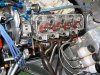
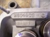
I have just torqued up my new ARP studs - part 254-4110 - on my C3 heads. Then I went to check the fit of the rocker arm mounts, and discovered that those very same studs are in the way!
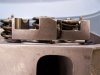
Have I got the wrong studs, or is it a recognised necessary modification to shorten the studs to allow proper fitment?
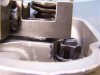
Also the heads have built in steel load spreaders at the top of each stud hole. Should the ARP washers be left off? I have used them, and the nuts are also in the way of the inlet rocker mount, so I need to either leave off the washers or use smaller height nuts.
Any advice appreciated.
 

Attachments

  • 100_2174.jpg
    100_2174.jpg
    54.1 KB · Views: 776
  • 100_2207.jpg
    100_2207.jpg
    30.5 KB · Views: 721
  • 100_2212.jpg
    100_2212.jpg
    46.2 KB · Views: 753
  • 100_2215a.jpg
    100_2215a.jpg
    38.1 KB · Views: 771
Lee,
When using the Jesel Rocker setup that you have, you will probably have to use spacers between the rocker mounts & mount bosses of cylinder head ( pictured in post above ) in order to obtain the correct rocker geometry and wear pattern on the end of the valve stem. You should do this first using an adjustable length pushrod before ordering your pushrods. This may require you to machine either the length of your head studs or to machine the rocker mounts at that point for clearance. I would also suggest that you obtain a set of 12 point head stud nuts with integral washer to do away with the washer you currently have and allow the use of either 9/16 or 5/8 socket.
The Jesel system with limited adjustment range at end of rocker arm mandates that you go thru this setup each time you change cylinder heads or alter stack height due to machine work etc.

Jac Mac
 
Thanks Jac Mac
Are these the nuts you are referring to? Bolt these down straight onto the heads? Does anyone make the spacers if I need them, or is it just a case of making them up at home?
Why do ARP supply these stud kits like this. Why not supply studs about 5 threads shorter with the other nuts, and then they would fit all applications?
Or would that just be too simple??!!
 

Attachments

  • arp-300-8330_w.jpg
    arp-300-8330_w.jpg
    20.6 KB · Views: 631
Yes thats the 'nuts' The steel insert in your heads is a change made to try & prevent the alloy nut/washer face collapsing particularly on the outboard studs which suffer from exhaust heat. Only torque/retorque those heads cold-not hot.
Now have you tapped the block with a bottom tap and machined a round or bullet end on the 1/2" unc /block end of your studs so they sit in the bottom of the block stud holes rather than the last thread of the stud, this might help lower the stud slightly & is the correct way to install studs in a block with blind stud holes.[ your ARP studs should have this feature ]
The Jesel Rocker System usually comes with a selection of spacing washers and each in/ex pedestal was seperate. Nascar teams found it advantagious to weld each pair like your photo " -after they had worked out the correct spacer height for each pedastal-". That particular setup then became part of 'that' head combination- except in their case they have it down to a fine art with the equipment to repeat machine cyl heads to the same requirements.
Now I note that you have been replacing valves etc with others of slightly different lengths- Im sorry but you may have to go thru the process of setup again to arrive at the correct geometry.
I found it easier once I had determined the spacer thickness reqd to cut a 1" strip of steel or stainless of that thickness and drill 7/16" holes in the strip at about 1.25" intervals before cutting again to give you enough square spacers to do the job. This is why its important to ensure all your valve stem heights are the same etc, or you end up needing diferent spacers for each pedestal

Jac Mac
 
Last edited:
Thanks Jac Mac. I'll check the bottoms of the stud holes and retap if necessary. I didn't notice bullet or round ends on the studs, but will arrange if necessary. Still don't understand why ARP supply the washers and standard nuts, if they might foul on the rocker posts.
Since the engine was supplied as is (apart from the 2 valves) that indicates that the previous builder only used pushrod length to set the geometry. From what you're saying, it is unlikely that the geometry will be correct without any spacers, and in fact unlikely that the pairs of posts are sitting correctly because they likely had different sized spacers under inlet and exhaust posts? I'll check to see if they sit properly on the bare head, and see if they do have different needs.
They are T&D rockers. I'll see if I can get a kit of spacers from them, and also their checking tool.
Thanks for your help.
 
The heads can also be used with 'conventional ' stud/rocker/guideplate with nut clearance built in so unless ARP make a specific T&D or Jesel stud kit [ unlikely ] this is why you have the problem. Also if you are running a different base circle cam, different deck height block etc to the original that the heads /rockers were fitted to everything will have changed.

Jac Mac
 
so thats why that weld in the second photo was there.. If I would have done that weld on my work.. well I might have been forced to search a new job.. It´s cold..
 
With the individual stud platforms of the head at a compound angle the weld has to be done in place on the head with the correct spacer's in place. Most guys dont want to spend any more time than necessary on the welder with all that expensive alloy / hardware in place. It is more a way of keeping the rocker to valve stem relationship correct and to be able to remove/refit without going thru setup each time than for any strength reasons.

Jac Mac
 
Lee, your studs appear little too long. Stud (and nut) top level should be bellow the rocker boss plan. There are two stud type: one for aluminum block (with long thread) and an other one for cast block (with shorter thread). Be sure that your studs are fully screwed in the block. If yes, you have tu cut them by 1/8" (about). Here below a picture showing the normal stud length. Good luck ;)
 

Attachments

  • yates heads.jpg
    yates heads.jpg
    84.9 KB · Views: 997
I suppose so maybee its bad angles too... its easy to change your mind with those welds give it a tap with a hammer and it´s undone. :)
 
Lee: I'm probably too late to help with your problem, but I show the fix for the exact rocker-arm stand-to-stud/bolt interence problem you "had." I hope you didn't space the stand up, which can cause rocker-arm geometry problems. As you may guess, one component supplier doesn't consider all the possibilities such as the one you encountered.

As for spacing up the stand, this shouldn't be done to make clearance to the head bolts/studs, but shimmed for rocker-arm geometry. I show in my book, page 154 of Racing Engine Builder's Handbook, milling the bottom of the rocker stand directly above the head-bolt/stud areas to provide clearance and allow the stand to be pulled down evenly against the head. We've found that this wasn't done on some engines, which resulted in the stands being bent and cracked as the stand bolts were torqued.
 
Back
Top