

You are using an out of date browser. It may not display this or other websites correctly.
You should upgrade or use an alternative browser.
You should upgrade or use an alternative browser.
Problem with coolant hose
- Thread starter Bill D
- Start date


Hi Bill,
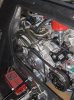
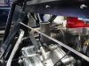
I imagine Fran has a fix for that") Attached pic shows our short accesory drive package that accomodates forward and low (correct) engine placement. This setup will run with an almost flat firewall panel, only about an inch protrusion needed to clear the water pump nose and a/c pump clutch. There is all kind of space for air circulation to minimise heat soak.
Attached pic shows our short accesory drive package that accomodates forward and low (correct) engine placement. This setup will run with an almost flat firewall panel, only about an inch protrusion needed to clear the water pump nose and a/c pump clutch. There is all kind of space for air circulation to minimise heat soak.
The A/C Bracket is a CAV Canada part that fits any small block Ford water pump and aligns with all pulley configurations, very trick part.
Your simplest suggestion would be a horizontally oriented water outlet fitting rather than the OEM Ford part pointing strait up, works in a Mustang but this is whole different horse. Could be custom fab part but simple enough to make. We do that kind of work too...
Cheers
I imagine Fran has a fix for that
Attached pic shows our short accesory drive package that accomodates forward and low (correct) engine placement. This setup will run with an almost flat firewall panel, only about an inch protrusion needed to clear the water pump nose and a/c pump clutch. There is all kind of space for air circulation to minimise heat soak. The A/C Bracket is a CAV Canada part that fits any small block Ford water pump and aligns with all pulley configurations, very trick part.
Your simplest suggestion would be a horizontally oriented water outlet fitting rather than the OEM Ford part pointing strait up, works in a Mustang but this is whole different horse. Could be custom fab part but simple enough to make. We do that kind of work too...
Cheers
Attachments
Bill:
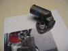
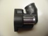
I had the same issue. I wanted to keep the thermostat in the 'standard' location, so opted to modify a standard thermostat cover.
Finding a thermostat housing that would fit proved to be a real challenge. We finally settled on a generic housing (Stant 31418) and then cut out a notch and re welded it with a 30 degree backward angle.
I had a local welder cut the fitting and do the welding. For a pro this is an easy job and he did a nice job. I did make very detailed drawings so there would be no confusion.
A 180 degree thermostat was used. A standard Ford 302 bypass hose was added.
Even with this set up, the thermostat cover protrudes about a quarter of an inch inside the car, so a small ‘bubble’ will be added to the removable fire wall, similar to the bump to clear the pulley. I estimate that I will cut out a section about 6" long by 3" high and bring it in about a quarter of an inch. It will have no effect on the passenger seat and should be fairly inconspicious. This arrangement is tight, but there is enough clearance to, hopefully, avoid any problems.
I will make sure that the rubber hose does not contact the fire wall to avoid any wear due to engine vibration issues before this project is complete.
I looked a long time for a prefabricated fitting without success.
Your hose goes the other direction, but I expect the same approach would work for you.
Since you have a ZF tranny the mounting location of your engine may result in a slightly different configuration.
If anyone comes up with a better solution that keeps the thermostat in its 'stock' location I would sure like to see it.
A couple of pics follow. More on on by build log. Good luck.
Chuck
Attachments
Ian:
Guess I need to eat my words. You appear to have a solution ready to go! Wish I had known about that before I went to all the trouble . . . . .
Queston: from the picture I cannot tell if the housing has room for a thermostat, although it appears to me that the thermostat would be external.
Chuck
Guess I need to eat my words. You appear to have a solution ready to go! Wish I had known about that before I went to all the trouble . . . . .
Queston: from the picture I cannot tell if the housing has room for a thermostat, although it appears to me that the thermostat would be external.
Chuck
Hi Chuck, Gregg, Bill
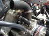
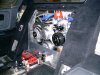
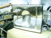
Here's a couple more pics of the same install. It's easier to see the angle of the firewall (30degees) and the low engine position. The bulkhead windows on virtually all GT40 replicas are in the same place so that's a better reference point to guestimate by.
On the intake manifold and thermostat, there is roon for the thermostat and it's a Weber manifold so the area around the thermostat housing isn't quite the same.
The picture of the engine side of the firewall panel shows the relief for the A/C clutch and lower water pump pulley. The top half of the water pump bump could have been taken out completely but wed already had enough fun with fiberglass.
Bill, looks like an electronic distributor, what is it? I tried the MSD Electronic unit but it was WAY TOO HIGH so we went with the standard part and a 6AL
Cheers
Attachments
Scott McDill
Supporter
I posted on Mark's thread then seen it here also.
I used a CSR housing
CSR Swivel Thermostat Housings - summitracing.com
This worked great for me.
Jeff Hamilton
I used a CSR housing
CSR Swivel Thermostat Housings - summitracing.com
This worked great for me.
Jeff Hamilton
Yes, Jeff, thanks! I ordered this one yesterday:
CSR Performance 9111C: CSR Swivel Thermostat Housings - summitracing.com
CSR Performance 9111C: CSR Swivel Thermostat Housings - summitracing.com
Jim Dewar
Supporter
Sorry Mark, I must be mistaken about it's function. I incorrectly thought it was the warm water exit from the intake through the water pump to the cars heater core. We plug both the thermostat housing and both water pump inlet and outlet tubes.
Again, I apologize for my incorrect post!
Again, I apologize for my incorrect post!
Last edited:
All,
PI Motorsports (principally a Pantera shop, also formerly a CAV dealer) in Orange, CA makes a bolt-on thermostat housing for putting a 351W into a Pantera, and also used on their CAV cars. It covers up the bypass orifice, meaning you would have to plug the corresponding inlet on the water pump. The main water hose exits 90 degrees to the right.
They have boxes of them on the shelf, as they are made in bulk. They don't list them on their website however.
Contact info is at Pantera, DeTomaso, PI Motorsports
I would presume that you would want to modify the thermostat to enable it to flow some water even when closed, since the stock bypass is no longer in play?
Similar threads
- Replies
- 74
- Views
- 5K
- Replies
- 4
- Views
- 1K