Remote Water Pump Block Adaptor for SBF?

Randy V

Moderator-Admin
Staff member
Admin
Lifetime Supporter
Hi, sorry if this has already been asked...

Does anyone make a SBF Block Adaptor for Remote Electric Water Pump applications?

Hi Sean,

Like you I was looking for something acceptable and I really found very little out there.. So I made my own Coolant Distribution Manifold from a Water Pump housing.

You can see how I did it on my website:
GT-Forty.com

Here's one snap-shot of the final product as installed on my Mock-up engine;
IMG_1377.jpg


I make fairly regular updates to the site and please let me know if there's something that interests you and need more information on..
 
Moroso also makes a nice unit. I am using one on my 351W. I did away totally with the water pump housing and I modified the front where the water pump sits to give it a cleaner appearance. I will have the pump mounted in the engine bay side wall. After I moved my engine forward, I found the pump was sitting in the drivers compartment next to my shoulder. Rather than swap the unit for a different style, I have adapted it to work with my arrangement using some of the Meziere adapters. Will check to see if Moroso has some as well. It will be installed this week. I will post some pics as soon as I get out to see it. I am also trying to find a pump controller that will allow me to use slow flow on startup and then full flow when the target temp is reached. Some of the guys have had leak problems with their aluminum radiators from the surge of temp changes.
Looking through the Meziere catalogue, the remote pump can have a single or dual outflow pattern allowing you to hook it up to the block inlets on the motor with the right adapters if you keep the pump in the engine bay.. They also have a setup for the thermostat bypass eliminating the Y that Randy shows on his site.

Bill
 

Attachments

  • P1010093.jpg
    P1010093.jpg
    62.6 KB · Views: 1,406
"I am also trying to find a pump controller that will allow me to use slow flow on startup and then full flow when the target temp is reached. Some of the guys have had leak problems with their aluminum radiators from the surge of temp changes."


This might not work with the Meziere pump. Works well with the Davies-Craig one though...

Davies Craig - EWP - Electronic Controllers
 
I have just ordered the controller and plan on adapting it to the Moroso pump. Will let you know how it goes. Some like Dave S have just let the pump run full bore, and put varying size holes(1/4") in the thermostat to allow some flow until the thermostat finally opens. He likes the way this works for him.

Bill
 

Jim Dewar

Supporter
I used the Stewart Components, Inc. inline aux. pump (55GPM) at the radiator outlet. I wired it to the fan thermo switch to come on @195*f /off @180*f with the fans but left the stock waterpump (retaining the stock belt configuration) to maintain the standard flow until additional cooling is necessary. I also wired a 3 position switch to allow override on the dash = 1-off 2-pump 3-pump & fan. This was simple and solved my problems idling in high temps. with A/C on. It also eliminated the need for computerized flow control devices.
 

Randy V

Moderator-Admin
Staff member
Admin
Lifetime Supporter
Looking through the Meziere catalogue, the remote pump can have a single or dual outflow pattern allowing you to hook it up to the block inlets on the motor with the right adapters if you keep the pump in the engine bay.. They also have a setup for the thermostat bypass eliminating the Y that Randy shows on his site.

Bill

Looking over their website all I see are Remote Thermostats that do not have a bypass.
Meziere Enterprises

There's got to be a way to keep the coolant circulating in the block until the thermostat opens or you'll end up with hot spots.. It would be better to not use a Thermostat at all than to run without a bypass in my opinion.

If the pump I'm using (50 GPM) turns out to be insufficient - I'll add a second pump to help it out.
 
i will be running the davies Craig setup, i had trouble finding the adaptors so i made them (in fact i need to polish the surface tonight!!!! ready for final fit.

I cut down a standard ford timing chain cover to make it look nice, bought a length of aluminium from ebay (£20), a 3/4 BSP tap (£5) and a hole saw. then from a plumbers merchant a pair of Stainless Steel 3/4 BSP male/male fittings.


i will post pictures tonight.
 

Ron McCall

Supporter
Big-Foot,Look back at my build thread and check out what I did. If there are no pictures there,I will post some here later.


Looking over their website all I see are Remote Thermostats that do not have a bypass.
Meziere Enterprises

There's got to be a way to keep the coolant circulating in the block until the thermostat opens or you'll end up with hot spots.. It would be better to not use a Thermostat at all than to run without a bypass in my opinion.

If the pump I'm using (50 GPM) turns out to be insufficient - I'll add a second pump to help it out.
 
Randy,
As I see it you have at least two options. The first is to run a thermostat that has a bleed hole in it and running the pump full time. This will bleed hot water from the intake until the thermostat temp is reached to give full flow.
Your other option is to make or build a gate that is operated either manually or via temperature that will run circulation between the block and the intake manifold. The heat of the water will actuate the gate to swing from the blocked line to radiator, to block the circulation pathway to the pump. then water would flow from the intake to the radiator, back to the pump, and then to the block. The solar industry used these devices to open vent panels in the crawl spaces of homes for circulation. They are just expansion joints or gates that the heat activates. Just takes a little tinkering. Just a thought???

Bill
 
As promised some pictures. Although not runing yet I don't intend to fit a thermostat and use Davies Craig controller unit to alter water flow according to engine temp (low temp low flow, high temp high flow).

The pictures are of the modified timing chain cover (modified means taking a hacksaw and dremel to the bits of the cover that only served to hold the pump).

The other picture is of the inlet adaptors. the black ones in the fore ground were the mark 1s, done with only a hand drill and a file. the one i plan to use is the shiney one (holes are perpendicular thanks to a piller drill and the 3/4 inch threads went better).

i was going to paint the new one but the i think i prefer the polished look.
 

Attachments

  • Timing Chain Cover.jpg
    Timing Chain Cover.jpg
    42.6 KB · Views: 929
  • Water Inlet Adaptors.jpg
    Water Inlet Adaptors.jpg
    37.8 KB · Views: 824

Randy V

Moderator-Admin
Staff member
Admin
Lifetime Supporter
Ron - Your solution looks pretty good as long as the -6 bypass hose provides enough volume that your engine doesn't have any hotspots.. Do you have any issues with blowing too much coolant into the recovery tank?

Ant - I like your mods! very nice...

Bill - I'm not sure that my proposed solution is much different or more complex than what you've suggested.

I'm attaching some pictures below that show the mocked up system.
The first picture is of the BMW-2002 80c Thermostat. Cost - $15
33cd_1.jpg


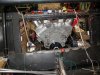
This is a mile-high view of the whole system mocked up with pipe-insulation in place of actual pipes/tubing. The bottom tube traversing to the rear of the car is the HOT tube.
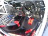
IMG_1266.jpg


Side view;
IMG_1270.jpg


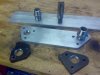
Y-Pipe where the Bypassed coolant will dump into the exit side of the radiator and therefore into the waterpump's inlet.

IMG_1268.jpg


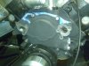
Closeup of the Thermostat - My cousin is TIG welding a piece of tubing to it that will cause the exit of the bypass to be straight rather than canted at an angle.
IMG_1267.jpg


About the Davies Craig units -
From what I have found they only flow 20 GPM. Since that's less than a standard mechanical pump (I'm told that's 30 GPM) I thought it to be insufficient.

I'll be the first to admit that I've never yet used a remote water pump before. I'm not cast in stone in my plans and open to what others may be doing as well..
 
DAvies craig do 2 models,

80L/min (21usG) for upto 5litres
110L/min (29usG) for high perf and 4wd

Also seems Maclaren F1 team use their products. FWIW i manged to get a an 80L model and controller on ebay, still boxed about half RRP. for that money its worth a try.
 
May I add a note of caution regarding electric pumps, whilst they can theoretically flow quite well their ability to produce pressure is not quite so good. I initially bought a meziere 55gpm unit for my car. we have subsequently changed to a remote nechanical unit, once again fron Mezier that has a marginally better flow rate but far better pressure.

I have a drwg of the system that we hope has addresed some of the issues that have been raised here and in a word an effective cooling system relies on being able to control pressure on both the output side of the pump and just as importantly the input side of the pump. If the pressure on the inlet side is allowed to drop then its boiling point also drops, as soon as that happens air / cavitation is inevitable with the resulting devastating effect inside the block / head assembly.

I will scan & distribute tommorow and would be interseted in the forums opinion,

The attached picture shows our remote thermostat housing with a bypass hose allowing continual flow past the thermostat to help with a more even temperature gradient and minimsing the opprtunity for caviatation when the system is cold
Regards

Iain, the original five minute expert !
 

Attachments

  • RIMG0047.jpg
    RIMG0047.jpg
    64.7 KB · Views: 790
When you relate back to the standard belt driven pump the flow induced pressure is created by the pump & therefore the cyl block and heads benefit from this--any drop in pressure in the suction/radiator side of the pump would be mainly caused by flow restrictions or insufficient rad core area. Since this coolant will be around 40° lower than that exiting the cyl heads it is not as critical in terms of boiling & will still be under nominal system pressure defined by the pressure cap.

Now in Randys ( Big Foot ) example its debatable as to whether the pump could be seen to be drawing the 'hot' coolant from the motor ( and therefore lowering the pressure in the block/heads ) or 'pushing' the coolant back into the block/heads ( in this case in order to create flow pressure it would need a flow restriction in the original t/stat area)-but in doing that you would immediately create a pressure drop on the radiator side of that restrictor and since this is the coolant exiting the block/heads is most susceptible to boiling and would create airlocks in the forward coolant lines/radiator if or when the boiling actually takes place. This is the last place you need an airlock on a car like this.
 

Randy V

Moderator-Admin
Staff member
Admin
Lifetime Supporter
I had always thought of Centrifugal pumps as PUSHER rather than SUCTION and it would appear that this may be backed up by the research (below).

Also - Please note that I am planning on using AN16 hose / connections from the intake manifold outlet to the 1.5" hot through pipe and and from the 1.5" cool through pipe.
This would provide some degree of restriction at the intake manifold's outlet - but there's a corresponding restriction on the inlet side where the coolant returns to the block under pressure from the pump.

I'm planning on using a 13# cap on the system as that's what I've used in the past and worked well - I've never been a proponent of the higher pressure systems.

Interesting when I wiki'd it I came up with this;
Pump - Wikipedia, the free encyclopedia
Centrifugal Pumps
Centrifugal Pumps are rotodynamic pumps which convert mechanical energy into hydraulic energy by centripetal force on the liquid. Typically, a rotating impeller increases the velocity of the fluid. The casing, or volute, of the pump then acts to convert this increased velocity into an increase in pressure. So the mechanical energy is converted into a pressure head by centripetal force, the pump is classified as centrifugal pump. (more in the article but somewhat less relevant)..

So given all of this - what say the masses?
 
Back
Top