

SPF GT40 POWER DOOR LOCKS
by David Miller
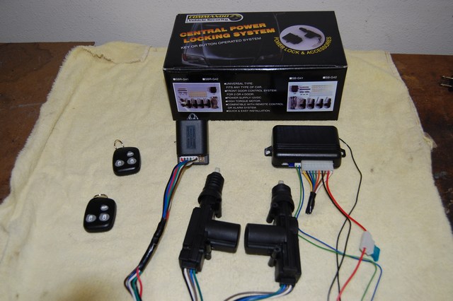
Many SPF owners aren’t concerned about the lack of door locks, but the thought of uninvited people trying out my seats or worse stealing them caused me to pursue keyless door locks. There are many web sites offering these. I chose slickcar.com and the Commando kit costs about $75. You get 2 actuators, a control module, a remote receiver, 2 remote transmitters, and wiring harnesses.
Hook up all the electrics outside the car so trial fits can be done. Instructions come with the kit, but I changed a few things. There are extra circuits for an alarm, starter interlock, and valet override. I deleted these. Basically both the remote receiver and control module need power and ground connections. Splice the blue pulse wire from the remote to the white control module wire. Ditto for the green pulse wire to the brown control module wire. Connect up the actuators and test their operation with a remote transmitter.
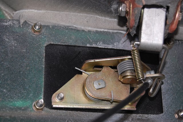
Remove the inner door panels on both sides. Photo B shows the door catch mechanism. The actuators are mounted on plates below this.
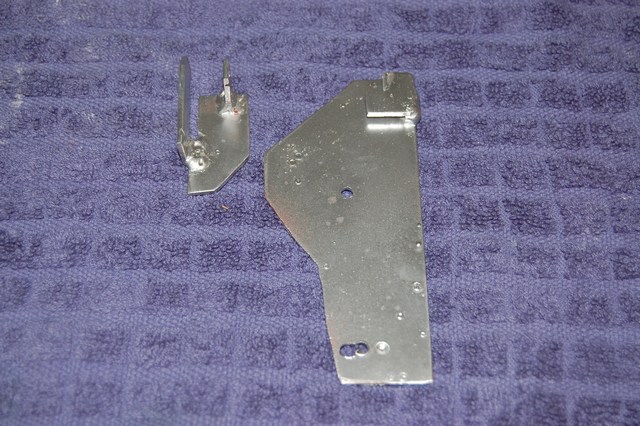
Fabricate a mounting plate and slider as shown in Photo C.
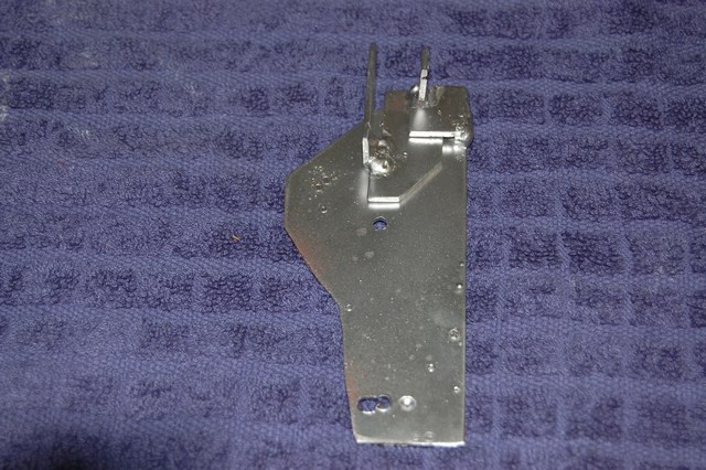
The slider is guided by a small tab welded on the mounting plate.
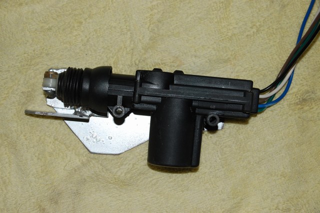
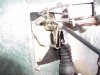
Photo E shows the actuator bolted to the slider mechanism.
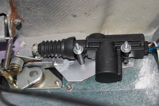
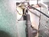
Photo F shows the assembly bolted below the door catch mechanism.
This takes a lot of trial and error, but basically the slider needs to move upward enough to block the door catch from rotating outward on locking. It also needs to be able to slide downward enough to allow the door catch to rotate on unlocking. This is a travel of approximately 3/4". Drill thru the door and bolt the top mounting bolt on the actuator first. Test the action of the mechanism with the doors open turning the door catch by hand. Flair out the top of the slot on the slider even though the photo doesn’t show this. Get the angulations of the actuator right so there is no binding. After tests show smooth action drill and fasten the bottom bolt. Then repeat the tests with one door at a time closed.
Finish by mounting the modules and wiring. Both boxes can be fastened with industrial Velcro behind the dash to the left of the fuse box. Fish the door wiring on each side up over the air ducts and down into the chassis boxes that the door hinges are attached to. From there pass them thru one of the front holes. Drill a ½" or so hole into the front face of the door. Using a grommet pass the wires into the door. After connecting these wires to the actuators return to the control module. Run power wires from the remote and command modules to the hot (red) connection on the ignition switch. Attach the 2 ground wires to a suitable ground under the dash.
With careful adjustment the actuators should operate reliably. What happens if they bind or the power fails? As a backup I’m attaching a wire to the slider bolt running it thru the back of the inner door pocket. In an emergency the side window vent can be removed (6 small allen head bolts). Reaching thru that you can access the wire inside the door pocket and mechanically release the actuator.
by David Miller
Many SPF owners aren’t concerned about the lack of door locks, but the thought of uninvited people trying out my seats or worse stealing them caused me to pursue keyless door locks. There are many web sites offering these. I chose slickcar.com and the Commando kit costs about $75. You get 2 actuators, a control module, a remote receiver, 2 remote transmitters, and wiring harnesses.
Hook up all the electrics outside the car so trial fits can be done. Instructions come with the kit, but I changed a few things. There are extra circuits for an alarm, starter interlock, and valet override. I deleted these. Basically both the remote receiver and control module need power and ground connections. Splice the blue pulse wire from the remote to the white control module wire. Ditto for the green pulse wire to the brown control module wire. Connect up the actuators and test their operation with a remote transmitter.
Remove the inner door panels on both sides. Photo B shows the door catch mechanism. The actuators are mounted on plates below this.
Fabricate a mounting plate and slider as shown in Photo C.
The slider is guided by a small tab welded on the mounting plate.
Photo E shows the actuator bolted to the slider mechanism.
Photo F shows the assembly bolted below the door catch mechanism.
This takes a lot of trial and error, but basically the slider needs to move upward enough to block the door catch from rotating outward on locking. It also needs to be able to slide downward enough to allow the door catch to rotate on unlocking. This is a travel of approximately 3/4". Drill thru the door and bolt the top mounting bolt on the actuator first. Test the action of the mechanism with the doors open turning the door catch by hand. Flair out the top of the slot on the slider even though the photo doesn’t show this. Get the angulations of the actuator right so there is no binding. After tests show smooth action drill and fasten the bottom bolt. Then repeat the tests with one door at a time closed.
Finish by mounting the modules and wiring. Both boxes can be fastened with industrial Velcro behind the dash to the left of the fuse box. Fish the door wiring on each side up over the air ducts and down into the chassis boxes that the door hinges are attached to. From there pass them thru one of the front holes. Drill a ½" or so hole into the front face of the door. Using a grommet pass the wires into the door. After connecting these wires to the actuators return to the control module. Run power wires from the remote and command modules to the hot (red) connection on the ignition switch. Attach the 2 ground wires to a suitable ground under the dash.
With careful adjustment the actuators should operate reliably. What happens if they bind or the power fails? As a backup I’m attaching a wire to the slider bolt running it thru the back of the inner door pocket. In an emergency the side window vent can be removed (6 small allen head bolts). Reaching thru that you can access the wire inside the door pocket and mechanically release the actuator.
Last edited by a moderator:
")