Designing a fuel tank - several issues/questions

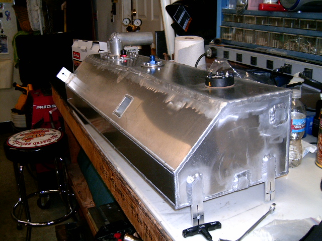
Okay - new thread - I decided to re-do the fuel tank since there were several issues I had with the first one due to its limited style.

Going to cheat and steal Howard's design :D

attachment.php


So hopefully some of you who are smarter than me can give me some ideas for several design issues I'm having

1) Is it alright to have the fuel level sender (swing arm style) around the fill port, such that a portion of the swing arm is underneath the fill port? The cobra has accostomed me to filling up at about 1/10 normal fill-up speed, so it's not like fuel will be pouring in on it and bending the arm, but I'm wondering if this is a really bad idea for some reason

2) My return line will just be a -10 fitting at the top of the tank. Since it's just dumping fuel back into the tank from the top, part of me believes that the area it dumps into should be baffled. Are there any "smart" ideas on the best way to baffle the return area, or just 2 baffles on either side of where it's dumping in?

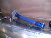
3) There is a hole in the fuel tank for transaxle cables to go through (beam welded onto both ends of the tank). It is 1.5''width; 1.5'' height in the above picture. I would enlarge to about 5''width, 3.5'' height. Is there any point I'd have to worry about fuel "Crushing" it? I mean, there's fuel ontop of it when the tank is full, and that fuel must weigh a bit......

4) Due to limited room I'm going to sump the tank in the centre, at the back.

But I have to build a sump pickup, as I can't have AN fittings at the bottom of the sump (not enough room). What my thoughts are is just to have a 3/4'' tube welded into the tank that goes to the bottom of the sump and sucks the bottom (then comes up, through the tank, turns 90* and has a -10 fitting welded onto it). The reason I'd design it this way (a tube w/ an AN fitting welded onto it, versus the AN fitting welded onto the tank) is to minimize height - if the fitting (straight) is welded to the tank, then I have to screw on a 90* fitting ontop of that. total height is ~3.5'' worth of fitting. To minimize this I have the tube come up and do the bend for me.

So 2 questions with the above

a - For less chance of future leaks, I'd have the pickup welded onto the tank. This means it's nonservicable. What's the chance a piece of crap could come up and clog the pickup, given the pickup size is 3/4''...that'd have to be a pretty large piece of crap......

b - Is there a better way to design this other than having a 3/4'' tube just sucking the bottom of the sump? For example, should I widen the tube at the bottom to make like a vaccuum cleaner mouth, so maybe the mouth itself is 1.5'' wide (that is sucking the bottom of the sump) that transitions to a 3/4'' tube?
 
1. You can get tube type senders (ISSPRO Product Categories) so that there's no arm to worry about.

2. I don't get the point, what do you see as a potential problem?

3. No. But why such a big hole?

4. Why not use and off the shelf internal surge tank? Or put baffles either side of the pump that have doors (Check Valve, TD150P) to trap the fuel in the pump area?

5. I thought I thought about things too hard, you're taking it to the next level ;)
 
There's nothing wrong w/ over-thinking.

Fuel safe kind of has something similar to my vacuum sucking idea

Pick-up, BPU06

A pickup that goes down into a vacuum sucker type thingie in the sump. Obviously mine would be much much bigger, but similar idea
 

Howard Jones

Supporter
We will need to know if you intend to run F.I. or a carb. The return comment leads me to believe you are using a F.I. system. The high pressure pump required for F.I. will need other considerations. If you intend to run carb(s) then the low pressure pump can simply draw from the top of the tank like I did mine. I also did not need a return line. My power requirements don't require that type of pump arrangement.

My tank is baffled into three sections of about 5 gals each. Also my fill tube ends in the tank with a roll over valve so that fuel that is pumped into the tank gets slowed down upon entry. I don't think this makes any difference one way or another. The vent line is also terminated with a roll over valve.

The pump feed line is -8 as is the vent line. Plenty for 400-500 HP. I would use a 2 inch fill tube if I did this again. The 2 1/2" hose is too big and not necessary for my use. Slow fill from a gas pump. Not a race type fill system.

Don't worry about return fuel aeration or some such stuff. The gas inside the tank will be sloshing around plenty.

Use a sender like mine. easy peizy
 

Doug S.

The protoplasm may be 72, but the spirit is 32!
Lifetime Supporter
We will need to know if you intend to run F.I. or a carb. The return comment leads me to believe you are using a F.I. system. The high pressure pump required for F.I. will need other considerations. If you intend to run carb(s) then the low pressure pump can simply draw from the top of the tank like I did mine. I also did not need a return line. My power requirements don't require that type of pump arrangement.

Since I'm not building a tank I don't really have a horse in this race, but I do have a question:

I will be removing the fuel tank from my Cobra replica soon to replace the sending unit with one of those ISSPRO models. Right now I am running a carb with a Mallory electric fuel pump, which I assume is "low pressure" since I need no pressure regulator in the fuel line.

However, I do recognize that EFI might well be a future upgrade consideration, so while I have the tank down from its perch, I'd like to be proactive and prepare for a return line.

Would it be advisable to have a return fitting fitted to the aluminum fuel tank and "plugged", perhaps with a cap on the fitting? If so, would the return line for an EFI setup be likely to use an A/N fitting? My tank is designed with a small elevated section where the fuel dumps in and where the pickup and sending unit are located.....would there be any problem with locating the return line on the raised section into which all of those fittings are located, or would I need to put it on the opposite side of the tank for some reason?

Sorry for the thread drift, I hope I haven't taken the thread too far off target with my questions.

Thanks!

Cheers from Doug!
 
We will need to know if you intend to run F.I. or a carb. The return comment leads me to believe you are using a F.I. system. The high pressure pump required for F.I. will need other considerations.

What type of considerations? Planning carb at the moment if it will fit but all pumps that flow for > 800hp require a bypass line, so I need the return line in there.

Btw, could you be so kind as to measure the height (base to top of tank itself, not base to top of fill neck) of your tank? I was reading your build log and you mentioned it was 9.5'' tall, but that can't be right - the distance from the crossbeam on the floor where the tank sits to the rear crossbeam is 9.25ish''......
 

Howard Jones

Supporter
My tank is 7 3/4" tall bottom to top. This includes the thickness of the material (1/8 X2). This will get you a top of tank width of 6 3/4", enough to mount a 6X4" fill plate. The total height of the assembly including the fill plate and inlet tubing less the mounting ears is a bit more than 9".

As I understand it. The high pressure pumps used for FI systems produce around 70PSI and do not draw uphill well. In other words mount them low below fuel level and pump towards the rest of the system. Carb's generally require about 2-7PSI (Weber's-holley's) and usually don't have trouble pumping up and out of the tank (uphill). The LP pumps can be mounted away from the tank and draw from it.

One way to do this with a FI system (there are many I would guess) is to pump from the main tank with a low pressure pump into a much smaller tank (less that a gal) and return the overflow back to the main tank. Then use a high pressure pump to draw off the bottom of the small tank and on to the rest of the system. The idea is to keep the inlet of the HP pump wet at all times. They do not like being run dry.

I think that kind of power will need a bypass type of regulator.

Carb, see this... http://aeromotiveinc.com/wp-content/uploads/2010/02/09Aeromotive_Carb_PowerPlanner.pdf

FI, see this...http://aeromotiveinc.com/wp-content/uploads/2010/02/09Aeromotive_EFI_PowerPlanner.pdf

From these guys....http://aeromotiveinc.com/

What I am not clear on is how to regulate/vent the LP pump/small tank. Anybody?

Here is a picture of my home made pickup. It draws from a 6X6X2" sump in the center of my tank.
 

Attachments

  • HPIM0915.jpg
    HPIM0915.jpg
    146.2 KB · Views: 463
  • HPIM0917.jpg
    HPIM0917.jpg
    213.9 KB · Views: 431
Last edited:
Thanks for the dimensions - not overly worried about fill plates, I'd have my friend just weld everything in place (Except the level sender) and be done with it. Less servicable, yes, but why would you have to remove the fill neck or anything?

For my pickup what I'd do is have him weld together a 3/4'' tube, have it bend 90* when it exists the tank, then weld a -10 fitting onto the end of it. I suppose the risk I take is some crud could jam up the pickup and I"d have a bitch getting it out (as the pickup would be welded into the tank) but how big a piece of crap do you need to injest to clog a 3/4'' pipe????

For my carb setup I'm either going to be using a Weldon Racing Pump (good for ~1600hp) or a Magnafuel setup. Still deciding at the moment, but either will draw realllllllllllllly well.


The one thing though I'd be worried about your setup though is the sump isn't baffled, so fuel can leave it in "extreme" conditions. But kind of late now to baffel it I suppose =)
 
Okay, re-design is happening. One last issue I'm trying to workout - the fuel pickup.

The way I'm going to have it done is a 3/4'' tube welded onto the bottom of the TOP of the tank that goes to the bottom sump area. Then the top area will be drilled out for a -10 weld-in fitting.

Now what I'm wondering if the distance from the bottom of the top of the tank to the bottom of the sump is going to be roughly 9''. The pickup tube will be welded onto the bottom of the top of the tank, but nowhere else...... with fuel sloshing around and banging around, what's the chance that the force of the fuel (even with proper baffles) will eventually crash against the pickup enough times and cause it to break off?

The only way I can see improving this is to weld the top of the pickup tube to the tank, and then weld brackets on the inside of the tank and the pickup, then bolt the pickup with metal lock nuts to the tabs for additional support
 
Dropped the tank off with my friend for re-construction.

The one tricky part will bet he pickup - he has an ingenious way to secure the pickup tube at the bottom (a set of "arms" to hold it in place), so that's good. The problem though is the pickup tube.

I'd like to make it removable, sot he current idea is:

-weld a -12 female bung to the tank
- get a -12 male fitting and weld a 3/4'' tube onto it. thread the male fitting into the female and bam, instant removable pickup.

HOWEVER, all female bungs are o-ring sealed. All o-ring AN fittings are straight cut (vs 37* flare) and usually have 2x the amount of threads on them. It would be impossible to weld a pipe to this and not damage the first thread or two such that it wouldn't thread in.

So I'm wondering what the solution is.

The best idea I have is to take a regular 37* flare'd fitting and stick the o-ring onto it. However, would this seal? I honestly have no idea....if it would seal it'd be dandy because you could weld the tube onto the flare, and the threads form the mechanical bond, and the o-ring forms the no-leaky seal. However, I have no idea if my logic is right or wrong here.
 

Howard Jones

Supporter
My tank is baffled into three sections. The center is approx 1/3 of the total volume. The small sump is to allow for sloshing around and still keep the pickup submerged. The sump will also keep the pickup contained in the center/bottom of the tank where I want it.

I also never intend to run it until the last 1/2 gal as you might in a race. I will keep it pretty much 1/4 to 2/3 filled from session to session.

I looked at a lot of fuel tanks and most have a flexible pickup hose with a pickup on the end of it. The dirt track guy I spoke with said that he and others use a flex hose because the hard line will break off at the top mount. There is a lot of leverage on the end of a 10 inch long piece of tubing. The forces applied to the end of the lever, with the pickup acting like a sail, by several gals of fuel washing around inside tank is enough to break it off sooner or later. At least he thinks so and so do I.

I believe that whenever possible its better to be able to service/repair systems by simple disassemble than by destructive methods. In the event of a failure, my pickup can be removed from the tank for hose replacement, for instance, very easily. Your idea will require you to cut open a used fuel tank and weld in a new pickup tube. The fill plate is so that I can replace the flapper valve or roll over check valve if necessary. Again easy simple service.

If you have ever cleared a used gas tank so that you can weld on it then you will know that just cleaning it will take a lot of work and time. Some people won't ever weld on a used gas tank.


To each his own I suppose.

You bring up a good point Howard.

However, I don't think (!hope!) the lever concept will apply to us.

Basically it'll be a female -12 bung welded to the tank. Then take a -12 to -10 union. On the -12 side weld on a piece of 0.7 pipe to the flare. Stick an o-ring on the -12 side, and screw it into place. To ensure the tube remains braced and goes to the proper place, we'll have several "arms" on the middle of the tank and around the sump. The pickup tube will go through these arms and be held in place by them.

That bracing should be enough to distribute stress as fuel is sloshing around.

And failing that, we can always play extract a .7'' tube through a .75'' hole :eek:

Although I suppose one could do the same exact thing, except use a fill plate cover in the area so if the pickup ever did break off, it would be easier to extract. Hmmmm.

The tank material doesn't seem thick enough to drill/tap for 1/4 bolts .... are you using a nut ring, or did you weld aluminum "blocks to the underside of it and drill/tap those so you have some real meat to bite into?
 
If anyone is going to complicate this it will be you Alex.
You think to much.

Use a 5mm alloy plate of a size suited to you and your space.
Mount the sender , fuel return and pick up in the plate.
You take the plate off and you have access to everything, as far as arms running off to hold the pick you are over complicating .
If something does need repairing you just made it so much harder to repair.
In any design you must access ,serviceability and ease of manufacture if you cant have all of this pick the things you want the most and compromise on the others.
If you want an internal surge tank make the plate larger and weld the tank to the underside and plumb through the top and or sides.

If you run your pickup tube through the plate and weld it on the underside then weld a weld on fitting over the top on the out side you will find it is less fussy.
If you wish you can protect the tube by placing a 2" or 1.5" tube over the top if it bothers you.
I have made plenty of tanks and have never had a tube brake out even with out a cover tube.

To fix the plate use m5 nutserts in the tank, make a nitrile rubber gasket, thread sealer and nylon washers for the screws.

By the way the fancy pick up thing is not really required, a tube with a 45deg cut on the end will work, if you want a sock on the end buy an EFI in tank pump filter and make your pick up to suit so it will push on the end.


Jim
 
Last edited:
What I am not clear on is how to regulate/vent the LP pump/small tank. Anybody?
Howard,
The fuel return line should actually go to the the small (sump) tank and another return line from the top of the sump tank back to the large main tank for overflow. This helps maintain a higher level of fuel in the sump tank and in turn, the small tank is being vented through the large tank as necessary when the sump tank is not full.
 
If anyone is going to complicate this it will be you Alex.
You think to much.

Use a 5mm alloy plate of a size suited to you and your space.
Mount the sender , fuel return and pick up in the plate.
You take the plate off and you have access to everything, as far as arms running off to hold the pick you are over complicating .
If something does need repairing you just made it so much harder to repair.
In any design you must access ,serviceability and ease of manufacture if you cant have all of this pick the things you want the most and compromise on the others.
If you want an internal surge tank make the plate larger and weld the tank to the underside and plumb through the top and or sides.

If you run your pickup tube through the plate and weld it on the underside then weld a weld on fitting over the top on the out side you will find it is less fussy.
If you wish you can protect the tube by placing a 2" or 1.5" tube over the top if it bothers you.
I have made plenty of tanks and have never had a tube brake out even with out a cover tube.

To fix the plate use m5 nutserts in the tank, make a nitrile rubber gasket, thread sealer and nylon washers for the screws.

By the way the fancy pick up thing is not really required, a tube with a 45deg cut on the end will work, if you want a sock on the end buy an EFI in tank pump filter and make your pick up to suit so it will push on the end.

Jim

Okay, but how to affix the plate to the tank. That's a problem becasue of the odd shape a nut ring would be very difficult to put into place. I see you say to use nutserts/rivnuts, but they don't sit flush with the top (i.e., when you pull them, they always have a lip/washer on the surface they're attaching to), so the gasket/plate wouldn't sit flush on the top of the tank.

The only way I could see around that is if you take the rivnut and weld it to the underside of the top of the tank. Which might work?
 
You can buy counter sunk riv nuts, in a 1.6 or 2mm sheet they will be flush.
If the sheet is thicker it just gets better.
M5 or m6 is as large as you will need, any larger they may not be flush.
I used m5 in 1.5 sheet with phillips head machine screws, allen heads look hard core untill you have to pull 30 off the bastards out.

I am asuming this tank runs L to R not F to rear like a 40.
One thing I would do in that tank is 2 walls say 300mm apart in the center, they would have inward opening doors on piano hinges.
As you go around a corner to the left the the fuel in the l/h of the tank will open inward and allow the fuel to enter the center area, the fuel in the centre area will close the door on the r/h wall and stop the fuel running to the right off the tank,this will control the movement of the fuel.
The walls do not need to be a super tight fit 1-2 mm clearance is fine,they dont even need to come all the way to the top of the tank 3/4 is fine.
It will work the same in the oposite direction naturally.
The piano hinge I always pull the hinge pin out and put smaller wire in so the hinges are real free.

One last thing when you are finished assemble the tank ,plug all the holes and outlets bar the fuel out or retupn and rig a radiator pressure tester up and pump a couple of pound into the tank(just till it pumps up slightly) ,spay all your welds and gasket areas with soapy water look for bubbles,deal with any issues before the tank goes in.

Jim
 
Last edited:
Never used those types of rivnuts before and I don't think my friend has either.

Other than it being a pitta, is there any reason why you can't drill 8-10 1/4'' holes and then weld regular aluminum rivnuts to the underside of the tank, then seal with 1/4'' bolts, nylon washers, and thread sealent?
 
Back
Top