Friends,
it is not that easy to fit a semi automatic synchronised gearbox in a car. It is a OEM matter.
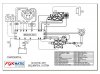
You will find attached the description of an automation system, semi automatic with up shifting and down shifting on demand, secured against wrong requestes. On top of it there is the automated drive away and the automatic down shifting during slow down manouvres.
For us this is called level 4. The level 3 does not have the automatic drive away which is handled through a third paddle on the steering wheel, but the automated clutch operation during shifting is there. In the level 4 there is another security gadget which is the clutch protection.
- If somebody is holding the car up hill without hill holder assistance, as soon as the sensor detects the 1st level of danger it will show on the dashboard....PUSH BRAKES...PUSH BRAKES....if this does not happen, then the system will pull the electric hand brake, open the clutch for down cooling and start on the hazard signal supported by intermadiate horns.
Pls find attached the level 4 which has an application cost of about 350.000 € if the engine is already drive by wire with a can bus for comunication with the gearbox GCU and the car is already equipped with an electric hand brake or an hill holder assist.
Have a look how it works, pls.
Wanni


AUTOMATION - COMPONENTS - DESCRIPTION.
1) ELECTRO-MECHANIC GEAR ACTUATOR.
The electric actuator for the control of the sequential gearbox comprises an electric motor and a mechanism for transforming rotary motion into linear motion of the element connected to the command lever of the gearbox.
Inside there is a thrust crank that performs a complete rotation returning to its start position, there is a crank stud positioned rotating with the action of the said electric motor. The stud engages a cam, made in the form of a template, fashioned in a plate sliding in a guide. The actuator can rotate clockwise or anticlockwise depending whether the gear change is up or down. A complete rotation, 360 degrees of the crank, realises a corresponding complete translation of the gearbox lever for one gear change producing the necessary stroke of the lever to pass from the middle position to the extreme position and to come back again. Definitively the actuator reproduces the same operation made by the hand of the driver that pushes (or pulls) the gear command lever in the cockpit. The electric actuator is connected to the gearbox drum command with a preloaded elastic joint. This element rigidly actuates a gear change operation until the reaction load of the syncro are equal to the joint preload. In this way it is possible to prevent possible dangerous overloads on the syncro, cutting off also additional inertia loads of the actuator. At the same time the actuator can continue its travel submitted to this elastic load, until the syncro completes its job and a complete gear change is possible.
The actuator is instrumented with a position sensor; in addition to the one on the barrel it is possible to recognize what is happening during gear change.
More gearshift operations are possible in a very short time with this electrical actuator that always rotates in the same direction until the last requested ratio is reached.
In this situation normally the clutch is realised only at the last gear.
Integrated on the electric actuator there is an electric motor speed sensor that allows a complete PID control strategy and a switch that identify the middle position of the template for recovery and safety strategies
2) CLUTCH ROBOTISED DEVICE.
The electric actuator for the clutch control comprises an electric motor and a mechanism for transforming rotary motion into linear motion of the hydraulic pump connected to the slave cylinder concentric to the clutch.
Inside there is a thrust crank that performs a complete rotation returning to its start position, there is a crank stud positioned rotating with the action of the said electric motor. The stud engages a cam, made in the form of a template, fashioned in a plate sliding in a guide. The actuator can rotate clockwise or anticlockwise depending from the necessity to control the clutch position. A complete rotation, 360 degrees of the crank, realises a corresponding complete cycle of opening and closing of the clutch. Definitively the actuator reproduces the same operation made by the foot of the driver that pushes and modulates the clutch pedal inside the cockpit. The electric actuator is connected to the clutch slave cylinder with a pipe.
The cylinder is auto regulating during clutch life as the traditional hydraulic pedal pump.
Similarly to the gearbox electro actuator, the clutch actuator is instrumented with a position sensor in addition to the one installed on the cylindrical slave cylinder. This solution permits to recognise what is happening during clutch life, and allows many safety and recovery strategies.
More opening clutch operations are possible in a very short time with this electrical actuator that can rotate in the same direction until the last requested ratio is reached.
In this situation the clutch actuator never reverses its motion, obtaining a fast action with a very low electrical consumption.
Integrated on the electric actuator there is an electric motor speed sensor that allows a complete PID control strategy and a switch that identify the middle position of the template for recovery and safety strategies.
TRANSMISSION AUTOMATION
1.) Functions, basic gear shift strategy,
Hardware, Software and Software development steps
Driver’s interface:
• Gear shifting: Pads on the steering wheel (up – down)
• Shift mode selection: “Manettino” on steering wheel or centre console
• Transmission pre-selection (P, N, D, R, etc.): switches on the centre console
• Selected transmission mode display: Display of selected mode and gear on dashboard
• Output for display:
clutch wear display
clutch overheating display
automation failure display
Gear up shift phases:
• Input to up shift a gear (throttle can be in any position)
• Feasibility check and strategy selection
• Dialogue with engine E.C.U. for revs and torque control
• Clutch opening (in according to selected strategy)
• Gear up shift (in according to selected strategy)
• Clutch closing (in according to selected strategy)
• Torque increasing up to target and selected strategy
• Return to management of engine E.C.U.
Gear down shift phases:
• Input to down shift a gear
• Feasibility check and strategy selection
• Dialogue with engine E.C.U. for revs and torque control
• Clutch opening (in according to selected strategy)
• Gear down shift (in according to selected strategy)
• Rear wheel spin control by clutch slide control
• Clutch closing (in according to selected strategy)
• Return to management of engine E.C.U.
Drive away:
• Brake switch on
• Selected first gear
• Brake release
• Clutch release modulation according to driver torque requested
• Brake on and throttle fully released: clutch fully opened
Gearshift strategy:
• By reaching maximum revs transmission does not up shift automatically.
• Down shift input in wrong rev conditions to ignore.
• Kicker during sport down shifting.
• Advanced down shift clutch management
• Automated down shifting during slow down manoeuvres and significant gap between actual gear and speed (by vehicle stopping, first gear remains engaged)
Shift Modes:
• Normal. Comfort oriented torque reduction / torque increasing and clutch opening / clutch closing.
• Sport. Time oriented torque reduction / torque increasing and clutch opening / clutch closing.
• Wet. Stability oriented torque reduction / torque increasing and clutch opening / clutch closing.
N.B.: No fully automated gearshift mode.
2.) Software: Basic Functions
• CAN bus management
• Driver management
• Strategy
• Mapping management
• Gear shifting for 3 driving modes plus 1 automated down shift mode
• Drive away
• Clutch overheating prevention management
• Fail safe strategies
• Auto check
• Diagnostics
3.) Hardware: Basic component description
• 32 bit ECU Microcontroller FreeScale Mac 7100 series (Motorola) automotive
• CAN bus
MINIMUM OUTPUT:
• Driver for n°2 full bridge D.C. Motor control (100 A peak value, 20 A continuous)
• PWM for proportional solenoid differential valve (3 A max.)
• Solenoid reverse lock (3 A max.)
• Solenoid key drum (3 A max.)
• Solenoid additional (3 A max.)
MINIMUM INPUT:
• n°2 counter for electric D.C. Motor
• n°4 counter for pick up speed sensors
• n°6 analogue input +n°2 additional analogue input
• n°16 digital input
SENSORS and SWITCHES description:
• n°2 analogue position sensors on actuators
• clutch position sensor
• air clutch temperature sensor
• drum position sensor
• oil temperature sensor
• brake switch
• n°2 paddle switches (N.C. and N.O.)
• pick up primary shaft
• pick up final shaft
• n°2 pick up for active differential (sx axle shaft, dx axle shaft)
• n°2 microswitch on actuator
• n°3 switches for modality selection
• n°4 switches for drive mode
N.B. The Hardware dimensions allow future upgrading and developments in Software tools, e.g. Active differential.
N.B. The Hardware dimensions allow future upgrading and developments in Software tools, e.g. Active differential.
4.) Software development steps
• Step 1: Gear shifting Normal, Sport and Wet mode, throttle off management, automated down shift management, clutch overheating prevention management, development diagnostics.
• Step 2: Step 1 plus fail safe strategies, auto check, diagnostics.
• Pre-production: Step 2 plus (definition of maximum number of failures permitted per km)
• Flashing
:bow::bow: Not that simple.

")