GT 40 gearbox identification

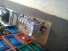
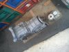
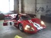
Hi, my name is Martin, I am working on a late 60 ies GT40 replica with chevy small block engine and a unknown gearbox which is broken....
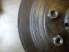
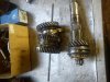
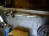
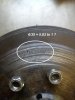
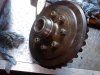
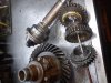
There is a "ford" sign on the crown wheel, but I cant find what model and year is it...
Can anyone help me please identify the parts by the pics

Sorry for my english
 

Attachments

  • IMG_20150320_154903.jpg
    IMG_20150320_154903.jpg
    117.4 KB · Views: 438
  • IMG_20150909_121011.jpg
    IMG_20150909_121011.jpg
    214.2 KB · Views: 414
  • IMG_20150916_172205.jpg
    IMG_20150916_172205.jpg
    197.9 KB · Views: 433
I think you are working on the MKIV Ford GT built by Ross Baker here in NZ many years ago.. The large gears shown are the ring & pinion from an early Ford V8 as in early-1934/39 Side Valve models. These gears are the basis of most Quick Change rear axles as used by Sprint Cars etc in Stock Car racing today. Do you have pics of the input & layshaft gears plus housing to help ID the rest of the parts and which parts do you require? I wont or don't have them but if I can ID them will point you to a source.

Nothing wrong with your English & 200% better than my Latvian:).

Actually I read somewhere that the original builder- Ross Baker- was looking for info on the cars whereabouts some time ago.

Heron Cars

about 1/3 of way down the page - Heron GT MK4

looks like 1966>> MKIV Ford Zephyr ( UK ) is / was the basis for 4speed trans and the spider gears & output shafts from the same car fitted to the 1934 R&P. Made their own castings- good Kiwi blokes!!
 
Last edited:
Some more pictures....
input shaft have been extended, splines are like ford, jaguar....
You can see that it is not factory made and the case casting is quite rough too
 

Attachments

  • IMG_20151007_102814.jpg
    IMG_20151007_102814.jpg
    154.8 KB · Views: 425
  • IMG_20151007_102827.jpg
    IMG_20151007_102827.jpg
    185.1 KB · Views: 335
  • IMG_20151007_102927.jpg
    IMG_20151007_102927.jpg
    97.2 KB · Views: 295
  • IMG_20151007_103543.jpg
    IMG_20151007_103543.jpg
    204.6 KB · Views: 337
  • IMG_20151007_103023.jpg
    IMG_20151007_103023.jpg
    154.3 KB · Views: 300
Hi Martins, What has actually failed in the transaxle that you need to fix or repair??? is it jumping out of gear or making odd noises etc? In the photos above the 4th photo is the mainshaft from a Ford MK4 Zephyr & gears.. this shaft has been shortened & re-splined to take the drop gear set that fit in the small housing of pic #1.
The last pic is the original Mk4 input shaft that has been extended with that longer shaft to pass thru the R&P section into the clutch assy.
In the 4th pic there is some wear on the mainshaft where low gear spin's which was an occasional problem with MK4 gearbox's, can you draw on the pics pointing out the areas you are concerned about or show us the broken parts if any?
Attached pic blue car type that was the donor for the gearbox section of your transaxle. Black Ford 39 coupe was donor type for the Ring & Pinion gears. Orange 'Howard' rotary hoe was the source of drop gears used at rear section of transaxle.

I see 'KASPA' reading this thread, he probably does not know it, but he now lives in the same area as the original builder of this car & transaxle.
 

Attachments

  • Ford_Zephyr_3008E_front.jpg
    Ford_Zephyr_3008E_front.jpg
    248.5 KB · Views: 245
  • 39_Ford-Deluxe-DV_13-RMSJ_001.jpg
    39_Ford-Deluxe-DV_13-RMSJ_001.jpg
    215.4 KB · Views: 349
  • 6320499644_32a02fedb6.jpg
    6320499644_32a02fedb6.jpg
    161.6 KB · Views: 291
Last edited:

Keith

Moderator

Attached pic blue car type that was the donor for the gearbox section of your transaxle. Black Ford 39 coupe was donor type for the Ring & Pinion gears. Orange 'Howard' rotary hoe was the source of drop gears used at rear section of transaxle.


Can't you be more precise Jac? I don't know, standards are slipping...
 
It looks like the Ring has a lot of wear on the back face from the photo. Does it have a brass or a steel button on a stud that keeps the pinion from climbing like a quick change? You can see the stud on the bell in this photo.
 

Attachments

  • th6EDQAMJI.jpg
    th6EDQAMJI.jpg
    7.9 KB · Views: 300
Can't you be more precise Jac? I don't know, standards are slipping...

Yes, I'm becoming aware of that Keith, can only do so much on a pension and the memory loss thing is probably about to kick in.. perhaps I should get a smart phone:idea:, but it would probably really only ask me questions if its a really smart phone...:thumbsdown:...

Martins.. I/we need to know which specific items you need to replace to help further.

Dave.... it does not appear to have external provision for a thrust button.
 
hallo, again
Thank you for your help!!!!!
The problem started with the oil pump- the pin snapped so the ring and pinion were running dry. they are worn out and blue (overheated). The rest of the box is ok except bearings and some sinhros.
I will try to find the CWP in states, maybe they offer one with LSD......
now at least I know what to look for, thank you again!!!!!!

Martins, if you have read the attached article in my first post the oil pump is sourced from the engine of an Austin/Morris Mini. Also the spider gears inside the CW carrier are modified items from the Ford Zephyr MK4 pictured so you will have difficulty in obtaining an LSD unit for that setup. You might have to purchase a DIY Kiwi hat and build your own LSD:).. Be very careful in whatever actions you undertake with that Transaxle... it may be the only one of its type in the world!!
 
Martins, I have been doing some research.. Your CW&P appears to be 5.83/1 ratio ( 6 /35) tooth count. That appears to be a 'Truck' ratio- not a car item? Can you measure the diameter of the Ring Gear and count the teeth on both R & P to be sure, plus number of splines on pinion. Also the distance from center to center of the two bearings in the bearing plate 2nd from rear. If that distance is 3.5" (~89mm) maybe you can use the six spline series of quick change gears to alter gear ratios.
 

Attachments

  • attachment4444.jpg
    attachment4444.jpg
    65.8 KB · Views: 274
  • attachment44.jpg
    attachment44.jpg
    154.8 KB · Views: 283
I wonder if Mr.Baker actually used two rings to make the carrier. That is maybe why the carrier seems has ratio numbers on it and wear from the thrust button Jac.
 
Maybe, but in this pic I think the pinion is more likely to be 10 spline and the ring gear appears to have one half of the diff/spider gear attached as one part..eg the split is at the cross pin for the spider gears. The ring gear in your post #12 above does not have the spider carrier as an integral part.

Apart from that the transaxle, apart perhaps from its length could be a viable option in that is made to bolt onto a conventional chev bell housing and with a bit of rework of castings and perhaps a more suitable R&P ratio and trans donor choice suitable for a variety of cars/engines.
 
Hallo, sorry it took so long! I had problems with heating at home, winter came early this year.....:)
The ring and pinion is 9/37 so it is 4.11, tried to find one like this but they are all 6 splines but mine is 10....
Thanks about the oil pump, I did not know it was mini!
 
I think this is what your looking for- BUT in order to fit it you will need to also buy a differential carrier which you can choose which LSD unit you desire, then you will have to buy a pair of stub shafts/output shafts to match as yours will not.

Speedway Motors 383 Open Wheel Page 61

for some reason page opens @ P59, so you have to go fwd one page, note slight ratio change to 4.12/1, they did that to get stronger pinion gear.
 
Back
Top