Garage wiring question....

Have a garage wiring question here my worn-out brain just can't figure out....

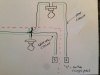
Here's the background. I'd like to add more lighting in my garage (who doesn't want more light in their garage??). There's an existing circuit with a single overhead light with the switch (single pole) on the end of the run - see diagram, everything inside of the red dashes. I'd like to add another circuit with another overhead light (maybe two) off this existing circuit, separately switched in a new double gang switch box in place of the existing single, preferably with the switch at the end of the new run.

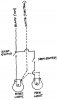
Will the wiring configuration in my hand-made diagram work? Hot wire is black, white/neutral is the light green, ground not shown (but will be included obviously).

Any help is mucho appreciato.
 

Attachments

  • Garagewiring1.jpg
    Garagewiring1.jpg
    100.7 KB · Views: 201

Randy V

Moderator-Admin
Staff member
Admin
Lifetime Supporter
I smell smoke.... :eek:

I'll try to draw you a diagram of what you have and what you want later tonight. There is no way it is wired as you have drawn...
 

Pete McCluskey.

Lifetime Supporter
I suggest you pay a registered sparkie to do the job for you. A small cost stacked up against you risking your house or indeed your life.
 

Doug S.

The protoplasm may be 72, but the spirit is 32!
Lifetime Supporter
What you want is a sub-panel. You will wire 240v out of your current main panel into the sub-panel, which is just another circuit box with just a few circuits...very cheap at Home Depot. I think I paid $17 for the one I bought and IIRC it has 4 circuits.

Home wiring is not rocket-surgery...go get a DIY book from your public library and you should be set. I switched over from 100 Amp/10 circuits to 200 Amp/40 circuits when I rewired the old 1920's era family home, have had zero problems so far and it has been 8 years now.

Cheers!

Doug
 

Randy V

Moderator-Admin
Staff member
Admin
Lifetime Supporter
Cliff,

Like Doug said, it's not rocket science. But, you have to be very careful and have at least a cursory understanding of how AC current works.
I ran out of time to draw the pics for you but here is a website that does a great job in simplifying the whole process.

How To Wire a Switch - Switch and Light at End of Circuit

And as Pete advises, hiring an electrician might be a good idea as well. Particularly if you have to meet local code regulations.
 

Dwight

RCR GT 40 Gulf Livery 347 Eight Stack injection
from your drawing I would suggest you get someone to help you.:laugh:

I would think you are going to use romex to wire the light, If so the switch leg would be white and the black is the hot wire to feed the switch.
The white wire to the light is your neutral and it goes on the white screw on the light (or white wire). The switch leg goes on the brass color screw on the light.

hope this helps

Dwight
http://www.gt40s.com/forum/members/dwight-albums-rcr-gt-40-picture1280-wiring.jpg
 
Dwight's correct, so long as you are talking about adding an additional switched light to the existing circuit. Here's a diagram showing another way to look at it. However, you need to be careful about the total load. Depending on your local electrical code, #14 wire is only allowed to carry 15 amps. Allowable current for #12 wire is 20 amps. You need to total up all the wattage that will be supplied by the circuit breaker and divide it by the voltage to get the amps. (For example, 1,100 watts of stuff at 110 volts will produce 10 amps of current.) If your existing circuit is getting maxed out, you may need to make a new, separate circuit back to the panel with a new breaker. Also, you always switch only the "hot" wire, and never use a white wire as "hot". Be sure of the code and be sure of the load, and if you are not totally comfortable get some qualified help. It's not difficult, but you have to think it through or you can zap yourself or burn down your crib!
 

Attachments

  • clifflite.jpg
    clifflite.jpg
    39.5 KB · Views: 144
Thank you gents, I understand the logic now of the circuits.....very helpful. I'll install the cans/lights as a slow-paced winter project (being careful of the total wattage/load on the circuit - thank you). Thank you for the circuit diagrams.

I'll wire it up. I have an electrician friend here in Seattle (professional electrician) who is a total gear head as well - will have him come over and check the circuit wiring before switching it on.

I understand the concern risk here....at least when I got in my old CAV I was only risking my own neck (mostly)....with wiring at your own residence/garage you're risking everyone's neck so it better be right!

Thanks again.
 

Charlie Farley

Supporter
Dwight,

You got me there.
Why are you wiring in two toilet bowls in your drawing ?
Water and electricity don't mix, especially when the ' crown jewels '
are in close proximity...
:stunned:
 

Dwight

RCR GT 40 Gulf Livery 347 Eight Stack injection
sorry Charlie
I assumed from Cliff drawing that he was using keyless light bases and just drew my picture to show them as keyless lights. My drawing is not an electrical schematic but a simple picture to help Cliff.

sorry to confuse you


Dwight
 
Back
Top