
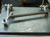
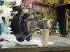
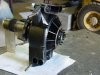
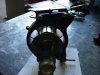
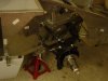
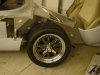
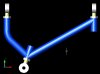
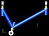
Here are a few pictures of the updated front suspension on my RF. I made some new arms to attach 2000 LOLA IRL uprights. I have 8 piston Brembo's and carbon/carbon brakes to go along with the uprights (will run steel on the street). I still need to make some steering pickup mounts. I am also updating the upper mount on the upright to not have the steering pickup point. This picture is of the Jig and upper arm.

You are using an out of date browser. It may not display this or other websites correctly.
You should upgrade or use an alternative browser.
You should upgrade or use an alternative browser.
New front suspension for my RF
- Thread starter RTIMTE
- Start date
Looks good! Did you do the fabrication work yourself? How about geometry changes? Other than allowing you to run the Lola uprights, do the changes "improve" upon the existing RF camber curves, bumpsteer, etc.? Finally, are you going to weld some gussets on the wishbone intersection?
I did the design and most of the work to make the arms myself. I did have my machinist friend do the welding. These are just tacked together to see how everything fits. The geometry as far as camber curve has more to do with arm length and pickup points. The arms are a little longer and the placement of the pickup points help a lot. As for bump steer, I am going to put the mounting point on the upright to all but eliminate it. The arms are made of 1" .090 chrome molly tube and RF's originals are made of hot rolled-electric welded mild steel. I am going to put a plate on the lowers for the shock mount/sway bar mount, but I don't think you need it on the top.
IMHO I would add gussets to all intersection points. It is probable that you will get flexure of the tube at those intersection points. This may lead to a fatigue failure of the tube. You could also add a brace parallel to the axis of the 2 inner pivots and as close to them as clearance will allow, smaller gusseting could then be used.
Chris Duncan
Supporter
It's hard to tell for sure from the pic but I looks like the axis of the inner rod ends aren't parallel.
When you adjust camber with one or both of the inner rod ends they are going to move closer or further from each other thus necessitating tedious shimming.
If you make them parallel this won't happen.
It's a shallow angle on the front rod end so you probably can't do what you did on the rear one with a separate piece. Might be easier to bend the front leg.
Also clamp some more before you weld, probably right at your 2 unclamped rest points. This thickness tube will warp quite a bit if not held rigid during welding. It will warp at least somewhat even with full clamping. You can heat to just barely dark cherry red and bend slightly to compensate if necessary. Turn off your shop lights so you can see when it just starts to get red.
Welding may burn the plating on your rod ends also, you might want to rig up a jig without them or rig some jig bolts or cheapy rod ends. You'll definitely want to re-tap your internal threads after weld.
That's an interesting looking upright. Are the fins and gaps to cool the bearing or allow cooling to the brakes? What metal is it fabricated from?
Chris Duncan
Supporter
IMHO you don't need any gussets except maybe at the front where the longest tube connects to the front threaded tube for the front rod end. If you were to move that connection further inboard you wouldn't even need a gusset there.
The loads on the upper arm are considerably less than the lower, just look at ball joint sizes on road cars. The rear leg is at such an angle that the weld contact area cross section is much larger than a 90deg. connection or a cross section of the tube. The front leg also has a large cross section at the rear weld so a gusset at it's rear isn't necessary either.
I assume this is 4130N in which case for an optimum job it should be normalized after weld, the HAZ becomes embrittled if this isn't done.
Chris Duncan
Supporter
CORRECTION
""It's a shallow angle on the front rod end so you probably can't do what you did on the rear one with a separate piece. Might be easier to bend the front leg.""
Should have read......
It's a shallow angle on the rear rod end so you probably can't do what you did on the front one with a separate piece. Might be easier to bend the rear leg.
Adjust camber with top outer rod end the non parallel condition of inner does not become an issue. It is not the length of the welded joint that is an issue it is the ability of the .090 tube to flex relative to the stiffer component that the rod end is threaded into at the front inner. Flexure will be occur at the toe of the weld at the 090 tube. Relocating the inner connection closer to the rod end as Kalun suggests will reduce flexure. Under braking a bending moment is induced, in the plane of the wishbone,at the inner and outer connections. The induced bending moment is highest at the inner Pivots and zero at the outer pivot. There will exist a bending moment at the outer connection. IMHO I would gusset at least the outer connection and relocate the inner or add gusset. The object is to gradate the stress levels and reduce fatigue. The other condition to be taken into account is dynamic shock loads from hitting a bump or similar object. This can produce acceleration of 3-5g. Have a look at suspension fab of most racing cars if you can, you may pickup some techniques to assist.
Kalun and Trevor,
I can't move the front upper control arm mount closer in as room is needed for the coil overs. I will then put in the gusset on both upper arm joints.
Thanks again for your comments. and I will post some pictures of the completed arms when finished.
I can't move the front upper control arm mount closer in as room is needed for the coil overs. I will then put in the gusset on both upper arm joints.
Thanks again for your comments. and I will post some pictures of the completed arms when finished.
Do the uprights have decent bearing seals? I have had bearing failures on race car uprights due to water getting into the bearings and washing out the grease, They usually run very low friction lip seals which will last fine for one race (500 miles) but need servicing regularly. If you can fit a more heavy duty lip seal I would reccommend it.
Carbon Brakes sound like a bit of fun, I will be interested to see how you get on with them...
Carbon Brakes sound like a bit of fun, I will be interested to see how you get on with them...
Chris Duncan
Supporter
Chris Duncan
Supporter
Similar threads
- Replies
- 4
- Views
- 947
- Replies
- 1
- Views
- 724
- Replies
- 10
- Views
- 1K