GTD rear suspention mod

Howard Jones

Supporter
I have wanted to try and do a mod to the rear of my GTD for some time based on the information on D Bell's website.

The basic problem at the rear of my GTD, and it seams D Bell's also, is that as the rear goes from normal ride height to full compresson (bump) the camber goes from the static setting, -1 degree, to about -7.5 degrees @ about 3 inches of bump travel. As messured at the outside of the tread.

Thats clearly too much camber change. It seams to cause the car to go from good grip at the rear on corner entry to snap oversteer as the chassis loads. If you add power on exit it just makes everything worse. Then as you catch the oversteer and the car resettles it goes back to decent grip again. The problem is that the grip limmit is very hard to predict.

Sooooo... I fooled around with moving the the chassis side upper pick up points. The D Bell site says to raise them to a point that would be in line with the webbing that braces the shock mount.

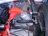
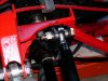
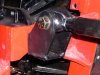
I did not want to cut into the chassis or weld on it so I made the mounts that you see it the pictures. They mount to the orginal brackets mounting holes so it is a straight bolt on. I also made some adjustable links so as to make camber adjustment easy.

The camber change now with 3 inchs of bump from static is an additional -3.5 degrees of camber for a total of -4.5 drgrees @ full bump.

How does it work? The car seams a lot more progressive now and it can really be steared with power now. I am not sure there is a lot more total grip now because I have no real way to messure it and I have no lap times to compair to but the car is not as scarry to drive and a lot more fun now.

My question to the engineers is about the bracket design. What do you think. Its made of 5/16" thick plate and a 2 X 2 X 1/4" angle. All mild steel. I think it is stronger than the orginal simple "U" brackets. They were mild steel also and 1/8" thick.
 

Attachments

  • 61295-HPIM0136aa.jpg
    61295-HPIM0136aa.jpg
    113.6 KB · Views: 747
Howard, I also did some work on the same wavelength as yourself, only my solution involved modifying the lower A arm instead of the upper arm, but the principal is the same. My only concern with your solution is the loading on the bracket bolts, which now have an additional side loading. Would it not be better, now that you have proved the benefit of your idea, to weld the bracket to the chassis, as you no longer require the bracket to be shimmable to adjust the length of the upper arm. I spent a lot of time on the drawing board with acres of graph paper plotting camber changes at different pivot points ( a CAD programme would have been much easier, and I have Autocad - I just cannot understand how to use it !! ) The solution is in both the position of the pivot point and the relative angles of the two arms. The GTD really does benefit from these modifications - well done. Frank
 
Hi Howard, to really come to grips with your suspention have good look at this software its not cheap but is excellent, they have a demo version on their site at the bottom of the page, they have imp or metric versions, it only lasts 10 days but if you have your brain engaged you can do a lot in 10 days.
http://www.performancetrends.com/SuspAnzr.htm

Regards
GraemeS
 

Chris Duncan

Supporter
""The problem is that the grip limit is very hard to predict.""

agree, and that's way too much camber gain. Also add to that the radial tire phenomenon of gripping up to a point and then suddenly breaking loose, compared the the more gentle transition of a bias tire.

""My question to the engineers is about the bracket design. What do you think. Its made of 5/16" thick plate and a 2 X 2 X 1/4" angle. All mild steel. I think it is stronger than the original simple "U" brackets. They were mild steel also and 1/8" thick.""

Your design looks good and I don't disagree with leaving it bolt on. You could find a skid pad or cone slalom and do some timed tests and try different camber gain settings. Eventually you might want to weld it but it's probably not necessary.

One thing that is maybe not optimum is your thickness. A bracket like this should be about 1/8" (.125") thick. A typical bracket with this amount of load on one of the original cars or a Mark V would be about 1/16" thick. Granted that's with a welded on doubler washer at the hole and flanged edges which are real labor intensive, but you get the idea.

You are getting some bending loads where the bracket bolts to the frame but I still think 1/8" would work. At this point though it looks like it sort of matches some of the rest of the frame and in order to save a meaningful amount of weight you would have to re-do all the too thick brackets, it's probably not worth it.

On another note I believe angle iron is usually weaker than most tubing, plate, bar etc.

What your looking for is 1018 or 1020,

Angle iron is usually 1010 or 1015 which is ok in this thickness for your application but you wouldn't want to use it in 1/8" in this situation.

Page 63 of Carroll Smith's "Engineer to Win" (1010) "is for lawn furniture, trailer frames and tooling only!"
 

Howard Jones

Supporter
Thank you Kalun, The idea was to try and figure out what would work and then have a proper piece made out of proper material and welded up by a pro. Do you think it might be better to "box" the open base area of the flats where they join the angle piece.

I wasn't interested in saving weight. I wanted to make sure it wouldn't break. I am still a little worried about that. I took them both off once already to carefully inspect the welds. All ok for now. The top link sees a lot less loading than the bottom A arms does but home made suspension parts worry me.
 
Great work Howard, You've done a really nice job. I've been thinking for a while about doing something similar (someday!). How much did you raise the pickup point? About 50mm ??

Also I wondered about something similar at the front, anyone got any thoughts on raising the lower wishbone pickup points? It looks like a modification could be made by simply drilling new mounting holes in the chassis... Anyone got any thoughts??
 

Howard Jones

Supporter
I haven't done the camber change measurments on the front but I don't think the front's problems are excessive camber change.

I do intend to mod the front also but so as to fix, bump steer, make new upper A arms with rose joints at the chassis ends so that I can make easy camber adjustment, and in the process allow for a wider range of caster adjustment.

Those seam to be the issues at the front of my GTD.

The mounting point is raised by 1.5" in the pictures using these brackets. They also shorten the lenght of the link by about 1/4"
 
Great Howard! I like what you have done.Fixed an issue without seriously hacking and chopping the chassis. By any chance did you measure any change in toe-in or caster behavior while making these improvements?
After we are road worthy, I intend to do similar mods to my GTD and am most interested in any improvements done by owners. For now though, I will concentrate on just getting it on the road.
 

Howard Jones

Supporter
I just reset camber and drove it. I did do a straight line check front to back before and after and I couldn't see any change in rear alinement. I will redo a complete alinement when I finish the front end this winter. I do not think that this mod will alter either caster or toe.
 

Chris Duncan

Supporter
"" have a proper piece made out of proper material and welded up by a pro.""

Lot's of "pros" don't know the diff between angle iron and tubing, shop carefully.

"Do you think it might be better to "box" the open base area of the flats where they join the angle piece. "

If you made it out of 1/8" you could although it's probably not necessary. The pivot through bolt clamping the heim and spacers strengthens the piece in the load direction you would box it for.

""I wasn't interested in saving weight.""

weight savings is free horsepower.

Take a closer look at the next racecar you see maybe specifically a dirt or pavement oval car. You'll see 1/8" thick brackets everywhere.
 
Just had a look at this software & seems quite comprehensive. However, has anyone tried the Susprog version for analysing suspension geometry? Again this appears to be a good & relatively easy program to use. You can download their trial version here: Susprog
Only US$200.
Re: Performance trends software, which basic geometry would be good starting point for the GTD chassis? Corvette?
 
Julian
With regards to raising the lower pickup points in the front end this is an area where problems can quickly occur if changes are made. You would probably change the roll center of the chassis at the front, and also you may introduce bump steer necessitating the rack being re-positioned to re-align it with the mounting alignment of the upper and lower pivots. Most of the changes you want to make can be plotted out on paper beforehand to see what geometry changes will occur, but every chassis is different and it may affect yours more (or less) depending on the original setup. Most of these chassis have very little roll and a lot of camber change is not desired as this is not needed to keep the vertical center of the tire as upright as possible. By Howard moving up his upper link he extended the virtual swingarm length at the rear which lessens the change in camber, If you look at the rear suspension in most GT 40's from an overhead view you quickly realize that the upper and lower trailing arms (I like radius rods myself) and their respective links (wishbones) form a wishbone assembly that has a pretty complicated geometry in itself. So in just raising the rear transverse link to eliminate some camber change also changes the anti dive/squat settings on the chassis. Get some info on suspension geometry, and you will see a little goes a long way as far as changes. Most of this is all common sense stuff and you guys sound like you are very capable of handling it without turning you car into what we like to call a "Flexible Flyer"
Good Luck
Phil
 
[ QUOTE ]
Use the classic sports car and 60s racing car rear suspension.

[/ QUOTE ]
Howard or Graeme,
Can't find any 60's race car set-up in Performance trends, am I missing something?

I raised the top rear link (inboard) by 20mm & this made quite a difference to camber change. However, I haven't used the car under race/heavy cornering conditions so can't be certain this is the best set-up.
 
I don't think that the GTD rear Camber change issue is truly a universal issue. Tire/wheel/air pressure combo's with relation to body roll will have greater handling effects than the Camber angle through the travel. Case in point; Running bias/ply (Hoosier street TD treaded vintage type race tires) and a relatively stiff rear spring with 15" wheels will have a tall sidewall that will "roll" under with cornering loads. Because the tread rolls under, tire pressures and additional camber may be needed to keep the tread as flat with the pavement as possible.
Likewise if a low profile sidewall racing slick is used with a 19" wheel, the camber gain will actually cause the outside of the tire to loose contact, therefor shrinking the contact patch and therfore grip.
I am running 300# rear springs, no rear sway bar, 15" wheels, BFGoodrich TA @ 28#, Stock rear GTD suspension, and 5" rear ride height. My testing so far has shown only 1" of shock travel during maximum cornering, and relatively even tread temps. I don't have a cornering "g-force" measurement other than that even with an Armandos 8Qt baffled race oil pan I lose oil pressure. (3 qt Accusump has been added)
To truly tune YOUR suspension you need to take temperature readings across the tread width of your tire immediately after coming off of the track to learn what kind of stress the tire is going through.
Derek Bell's site has good information but I don't remember it covering spring rates, tire size and type, or tire pressures. So what I am saying is there is no universal "fix" for any given cars suspension that will work with all tire, wheel, spring, and track combo's.
 
Totally agree Andy as every car has it's own suspension geometry traits.
I use 17" rims with 285/40 rear & 245/45 front tyres with 25mm front & rear solid anti roll bars with 350lb rear springs & 275lb front springs. I am not convinced this is the best option especially re: roll bar settings & having done some line drgs to simulate fornt & rear suspension geometry I would like to confirm my findings using computer software. After all, a computer has better diagnostic capabilities than human intuition doesn't it? /ubbthreads/images/graemlins/tongue.gif Or at least that's what my physics teacher told me!!
 
Paul
Software and physics equations use assumptions, variables, and rules/constants. The software is as good as the human who wrote it, the human who measured/determined the variables, and the acuracy of the assumptions. The most sucessful experiment identifies ALL the variables and carefully measures the effects of one variable at a time until trends can help predict outcomes.
Our first order of business would be to create even tread temperatures during our intended use.
Start simple (free$) with ride height, tire pressures, and compression and rebound settings.
If an extreme of one of those variables is most successful then consider a mechanical change. (ie. Most even grip when shock compression is maximum may indicate a need for stiffer spring or opposite end sway bar increase)
The software may give you a better point to start from, but ultimately the devil is in the details of trial,error and learning to predict outcomes from given changes.
 
Back
Top