Manifold Vacuum Fitting

HILLY

Supporter
Gents,
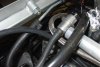
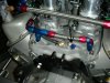
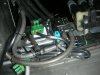
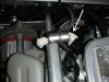
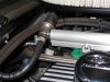
Would anyone running the RF supplied eight stack manifold be able to advise on the purpose of the second vacuum fitting located at the rear of the manifold. The 5/16” 90º fitting has been used for connection to the manifold air pressure switch and the carbon canister valve.(As I have installed carbon canisters). The purpose of the second 3/8” straight fitting is a mystery at the moment?? Any help would be appreciated.
/ubbthreads/images/graemlins/help.gif
 

Attachments

  • 80836-Man01.JPG
    80836-Man01.JPG
    215.3 KB · Views: 391
Hi Hilly,
On the two fittings into the manifold, the left one i have going to the fuel pressure regulator on the end of the left hand fuel rail, and the right manifold fitting i have to the right hand rocker cover breather.
jerry.
 

HILLY

Supporter
Thanks gents. Spot on as usual.
Though this raises a couple more questions.
Jerry, did you incorporate carbon canisters in your fuel system and if so where did you draw the vacuum lines for the MAP switch and CCV. Secondly is the vacuum connection to the rocker cover critical?
I think what mislead me bit was the size of the fittings. The 5/16” fitting was logically for the 5/16” requirements of the MAP switch and CCV but the 3/8” fitting had me stumped. The barb on the pressure regulator (Indicated by the white arrow, if I am correct) is only about 3/16” so I will probably use a reducing bush to adapt a 3/16” barb tail to the manifold as I doubt that a 3/8” BSP x 3/16” BT would be a standard fitting.
Jim, I have pretty much stuck with the standard RF set up and unless I am badly mistaken there is no prevision for a brake booster in my system?? Although now would certainly be a good time to find out that I was wrong. Thanks for the comments on the car. It has come together fairly good so far but as I am new to this game I would certainly do some things differently next time. Quite some time ago I started a build thread but because my build took second place to work the progress was fairly slow and I did not maintain the progress updates. I might go and see if I can find it and add a couple of progress photo’s.
Thanks again guys. Much appreciated.
 

Attachments

  • 80888-Man03.JPG
    80888-Man03.JPG
    155.1 KB · Views: 382
I have a standard RF 4-barrell manifold, not 8, so there may be differences. Plumbing was checked at the factory.

At the end of the fuel rail, as pictured, the left connection is for the fuel-return hose that goes back to the fuel collector tank. The right connection goes via a tee to the manifold below the air filter (which obviously you won't have). From the tee, the hose goes to the MAP.

There are three hoses connected to the manifold below the air filter: one towards the rear of the car going to the PCV valve in the rocker cover; the other two are towards the front of the car, one going to the MAP and fuel rail as described above; and one going to the CCV (the connector in the middle of the CCV).

The other hose on the CCV goes via a tee to both carbon cannisters. Each carbon cannister has three hoses: one connected to the CCV; one to the respective fuel tank; and one to the ground (overflow).

There is no brake boost on a standard RF.
 

Attachments

  • 80891-engine2.jpg
    80891-engine2.jpg
    158.6 KB · Views: 372
hi Hilly,
my injection system dosnt use a manifold air pressure switch, and the carbon canisters dont have vacume connected to them. I have the RF set-up- pumps, manifold, throttle bodys etc, but im using Omex electronics. The connection to the rocker box isnt critical, some say its better to have a slight vacume in the crank case,some disagre. my way of thinking is that if its under slight vacume then there is less chance of oil leaks from positive crankcase pressure. i may be wrong, but its working so im happy! /ubbthreads/images/graemlins/banana.gif
jerry
 

HILLY

Supporter
Thanks Kym. Your description is spot on.
Jerry, I tend to agree with your negative crankcase pressure logic. And if it’s working don’t fix it.
 
Negative pressure in the crankcase will give you a boost. I have the complete article if any are interested. Click on ATTACHMENTS for a clearer pic.

Bill
 

Attachments

  • 80976-Suction.jpg
    80976-Suction.jpg
    145.3 KB · Views: 381

HILLY

Supporter
Bill,

It would be interesting to know what the ‘ideal’ prescribed vacuum is and what is actually achieved via the manifold connection as in Jerry’s set-up.
I assume that the vacuum pump / relief valve set-up will provide a constant crankcase vacuum regardless of the operating conditions where as the manifold connection will have a fluctuating vacuum throughout the RPM range.
Although there is not a huge gain, Jerry’s set-up is virtually cost free and every little bit helps and all adds up in the end.
 

Peter Delaney

GT40s Supporter
Hilly, I have the same 8-stack as you and originally just used one of the vacuum ports for everything. This did not work well as the power brakes screwed up the ECU's MAP readings. We then stuck the brakes onto the second vacuum port & all was resolved.

With everything daisy-chained off the one port, the "big users" of vacuum tended to affect the "small users". It appears that there is enough volume in the vacuum tank under the manifold to cope with things, providing the big & little users are fed from the separate ports.

I now have things split as follows & it all works well :

Port 1 :

ECU MAP input
Fuel pressure regulator

Port 2 :

Power brakes
Carbon cannister purge valve
Bleed from rocker cover (approx 1/16" orifice)

Kind Regards,

Peter D.
 

HILLY

Supporter
Pete,
Thanks for your input.
I currently have the MAP sensor and CCV drawing from the same line. I was now going to add the fuel pressure regulator to this line as well but I was unsure of the effect that the two carbon canisters would have on the function of the ‘small users’ as you have described, that is assuming that the carbon canisters are actually ‘big users’.
Regardless I think that your set-up looks to be the best approach so will reconfigure my plumbing to reflect your arrangement. This will eliminate any trial and error. The only difference is that I will not have the requirement for the brake booster.
Thanks again.
 
The article is about vaccumn boosters, and yes the pressure is preset at the valvle cover. The bleed setup to the intake is very low pressure and is actually a balance between the negative pressure of the intake manifold and the positive pressure of the crankcase, and varies with the position of the throttle. So they have a tendancy to cancel out, or at least be fairly neutral. The vacumn pumps are pulling all the time against a preset pop off if you will. Notice the gains increase as the amount of vacumn pressure goes up. Be sure to click on the "Attachment" button for a clearer pic.

Bill
 

Attachments

  • 81111-Suction2.jpg
    81111-Suction2.jpg
    189.6 KB · Views: 395

Peter Delaney

GT40s Supporter
Hilly (another Pete, I see !) :

My carbon cannister & purge valve was a rego requirement - it all had to be seen in place & connected. However, being a "cheapo", I bought the basic Autronic ECU & it only has 1 aux output, so it got used to control the purge valve (mind you, it was only set to kick in at 6000rpm to ensure that it didn't blow in the middle of the emissions testing !). Once rego was achieved, I changed the aux output to drive the rad fan relay & just left the CCV connected in the closed position. Every few months, I'll do a manual purge of the CC with the air compressor.

I'm not sure what triggers off the CCV in a stock RF/Motec setup, but I am sure that it is "big user" of vacuum when opened - best kept separated from the MAP & regulator vacuum feeds.

Kind Regards,

Peter D.
 

HILLY

Supporter
Cheers Pete. (There can never be too many of us ;) )
The reworked plumbing is already underway.
Geezzzz I hate that word ‘REWORK’
 
Last edited:
A little late here, and perhaps covered, but I didn't see it a quick review...here in America I was told we don't need the carbon canister, so the one fitting goes to the MAP, the other goes to the right hand rocker. One thing that is different on mine (I have the DC&O manifold) is that on the fuel pressure regulator, only one hose comes off which becomes the return line for the fuel. The other end is left open with no hose. I asked the factory about it, and that was what they recommended, although they did say if I wanted I could run a 'bleed' line off to below the engine.
 

Attachments

  • DSC06320.JPG
    DSC06320.JPG
    51.5 KB · Views: 348
I thought that the fuel pressure regulator needed the vacuum line connected to function properly. It keeps fuel pressure referenced to manifold pressure.
 
Back
Top