Programmable EFI Questions?

Chris Duncan

Supporter
Accel Gen7 ECU, TWM induction, FAST Edist DIS.

Was wondering if there's a good book on programmable EFI? Looking around and can't find anything specific. Already have "Electronic Fuel Injection" by Ben Strader. It's good on theory but not on any hands on blow-by-blow explanation about specific tuning. Like what specific steps to take from start to finish when building a map.

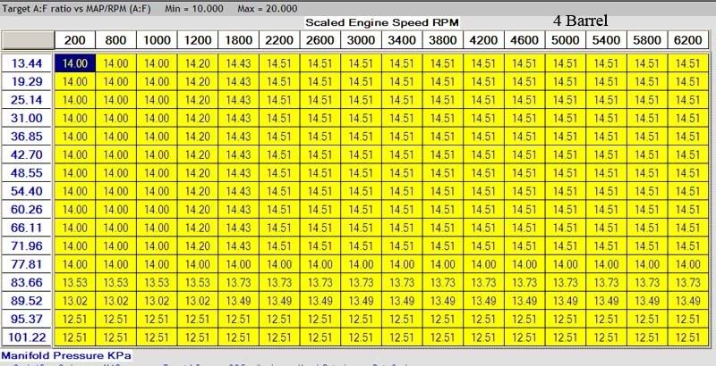
Originally was trying to use the auto-set function within the Gen7 software, but was running very rich. Tried all the possible combinations but nothing worked. Talking to the guys at Accel and find out that the auto-set feature only applies to 4 barrels and not ITB's, although this wasn't stated anywhere.

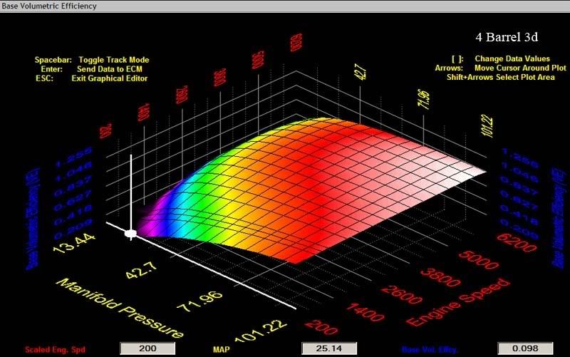
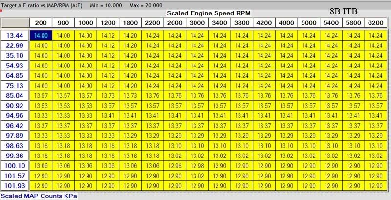
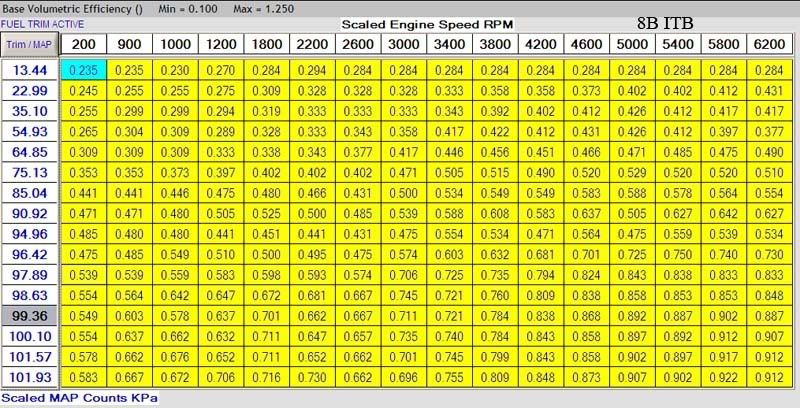
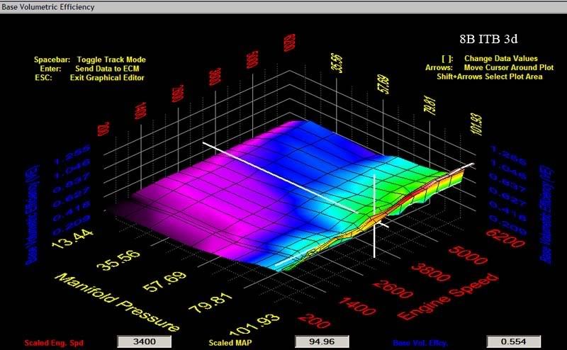
Well they sent me a map for an ITB setup and in 3D it looks totally different from the 4 barrel map. I'm just wondering how they arrived at this difference?

Another specific question, I have a mid range stumble-pop-backfire. It happens between 2,000 and 2,700 rpm. Under light-moderate acceleration. Very light accel or heavy accel and it won't happen. Outside of this rpm range it won't happen.
 
Last edited by a moderator:
Hi Kalun,

I run the Gen7 4 BBL on my 351-W and is a daily driver. Do you have a copy of your tune file you can send to take a look at? I'm not sure about the ITB set up though.

I have a friend who is a trained Gen7 tuner and he may be able to help you. Let me know if you want his contact information.

Leonard
[email protected]
 

Ross Nicol

GT40s Supporter
Kalun
Please don't treat me like a fool but your'e a bit scary when you make "please don't tell me" statements after questions in other threads.
I admit I don't know much about the gen7, but you seem to have asked about fuel injection and you have referred to Maps. I have come a fair way with my knowledge on fuel injection/engine management so I'll pass on a couple of Ideas. There are 2 important tables/maps, one for fuel and one for ignition.The fuel map basically has values that indicate the time in msec that the injectors will be open and a map is made up of many of these variable points which can be changed for all combinations of engine revs and Load (load basically being throttle opening). The problem is if you compare maps from similar engines and you expect them to be the same, you may have ignored things like:
injector sizing,overall trim capability, fuel/gas pressure,exhaust system etc etc.
My 2c worth anyway

Ross
 
Accel Gen7 ECU, TWM induction, FAST Edist DIS.

Another specific question, I have a mid range stumble-pop-backfire. It happens between 2,000 and 2,700 rpm. Under light-moderate acceleration. Very light accel or heavy accel and it won't happen. Outside of this rpm range it won't happen.

I have not played with your system so I cant be specific.
But you have to look at the maps as load vers rpm.
At 2500rpm mid throttle let us say it is at 50% load
At part throttle it is 10%
At full it is 100% load.
It is to lean at 2500 rpm with 50% load.
It is related to the load sites at 2500rpm,it may have 10 load sites at that rpm.

Best way is a dyno.
No accelerator pumps.
Start at the bottom and move up through rpm and load, holding on specific load rpm site to make adjustments.
Ignition you should look for max torque figures if it has a rattle you may have to drop a deg or 2.
Start safe to much fuel and not enough timing is good if you are learning.
I have no idea about your engine but a good engine will want about 30-32 deg max.
You can give it more timing in the lower to mid range rpm with lower loads say 30-50% this will sharpen it up, but you will have to feel that out youself.
Fuel you should be using a meter A/F 14.7s on cruise is ideal full load you will get into the 12s.
These are all ideal readings and eng set ups will change things.
Do accel pumps last on the road by stomping throttle to different deg till you iron out any hesitations.

This is general I hope it helps.
Others will be able to add to this ,good luck.

A handy tool is to get a pair of ear muffs and drill holes in them make a stethiscope using rubber hose.
A copper pipe folded over on one end and drill a hole into the fold.
Bolt this pipe to the head around the intake manifold.
Put the hose from the muffs into the copper pipe.
This will allow you to here it ping.
Test it by putting in timing and get it to rattle so you know what it sounds like.
wear the muffs while tuning it will help.

Jim
 
Last edited:

Chris Duncan

Supporter
""Please don't treat me like a fool""

Ross, I would never do that, and anyone that would is the fool.

remember you're the one that described to me the importance of relays, and changed my thinking about that aspect of electrics. My GT40 has 10 of them now when only 4 were originally planned.

"" but your'e a bit scary when you make
"please don't tell me" statements after questions in other threads.""

Sorry, not my intent, just wanted to let people know I'm already aware of the hydraulic e-brake problems.

""The problem is if you compare maps from similar engines and
you expect them to be the same, you may have ignored things like:
injector sizing,overall trim capability, fuel/gas pressure,exhaust system etc etc.""

I "think" I understand that there are going to be differences, I was just wondering how the different settings are arrived at.

I'm looking for a detailed description of the methods of arriving at any given optimum setting.

For instance with the problem I'm having, how do I determine if it's a rich or lean condition? Does a wide band O2 react fast enough to tell if it's rich or lean? Is it better to do a data "snapshot" and look at it afterwards? Or can you see something like that in real time?

Is the base map going to correct a transitory throttle increase stumble? Or is that better addressed by an "accelerator pump" type setting?

One thing for sure, there are way too many variables with programmable EFI to allow a hit or miss approach.
 
Kalun_D;216217 Is the base map going to correct a transitory throttle increase stumble? Or is that better addressed by an "accelerator pump" type setting? One thing for sure said:
O2 meter live is fine.
You are going to each site from low to high rpm and load.
The previous figures in the fuel and timing sites will give you an idea of what to expect.

If you iron out the stumble on accel pumps and it is in the maps it will still be lean at steady throttle.

Attack it with a plan.
You dont want variables(pumps ect) effecting the base map.
Once the base map is good you add to that with pumps ,cold start enrichment,temp compinsation ect .

Jim
 

Ross Nicol

GT40s Supporter
Hi Kalun
I wasn't being totally serious with that dig at you, so no offence intended.Asking a question and then directing replies is probably a time saving activity.
I agree with Jim a wide band Lambda sensor is certainly the equipment used for tuning in real time.The rattle he refers to is detonation and it's destructive effects well known. It is common for a tuner to advance ignition until detonation is detected and then provide a safety margin by backing the advance back by 2° or so.
This is critical at heavy loads but quite a lot of advance is possible at light loads.Makes the engine run smoothly.
Motec use an accelerator enrichment table to add fuel to the base maps for correcting stumbles and I would be sure most units would have this capability too.
It is possible to tune a lot of the fuel load maps while driving the car with a wide band sensor, meter, and laptop computer but data logging can be used to tune as well by analyzing retrieved data.
A nifty feature Motec have is what they call Quick lambda, what you do is create a target table of A/F ratios, when the lambda sensor gets a match, the injector open time is set for that fuel map location and on to the next one it goes.Saves a lot of screaming engine time on a dyno.
I get a sense of accomplishment after understanding even a small part of these complex systems but I enjoy the challenge.When you think about the ability to tune A/F ratio for the whole rev and load range you begin to understand why a carby can not compete.

Ross
 
Hi Kalun.

I have experience on mainly Motec systems, but concepts are still the same.

Re your query regading differing maps for similar engines, I have wondered this too but other than the sizing of injectors, there are a couple of other things to possibly consider too. Firstly, I've seen engines both with and without a manifold referenced fuel pressure regulator which makes a big difference. On a motor with a pipe from inlet plenum to regulator, the fuel pressure is lowered when at idle due to the vacuum and then it increases the fuel pressure at wide open throttle, or even further if the engine is boosted by blower/turbo. The effect of a lower fuel pressure at idle or part throttle means that the FUEL MAP will require larger values to flow the required fuelling. Without the pipe connected, the values will be much smaller as the fuel pressure is then higher, but this can make the injectors difficult to control as they then need to open for much smaller periods so resolution of adjustment can be lost. At wide open throttle, the MAPS will look the same with or without the reference pipe.

There is likely to be a clear difference between maps for 4/8 throttle setups. The throttle position is normally a voltage that represents the angular position of the choke plate within the inlet passage. If both throttle types were set to a position representing 50% throttle (say 2.5v), then I would think the air flow available to an individual cylinder is going to be different for each motor/throttle type combination (4/8 barrell). Hence each FUEL MAP will have a different value at the same throttle position to give the correct fuelling for the different airflow.

Thus - if you mapped for a 4-barrell on a motor, then removed it and fitted an 8-Barrell setup, the MAPs would be quite different. All down to differing flowrates at similiar throttle positions...

Re-reading I hope I've not clouded the issue, but either way it's my 2c...:)

ps - I use a Motec Wideband Pro Meter which integrates easily with the Motec ECUs or can work standalone for other systems. Working alone it does not have any logging capability though which can help a LOT for on the road tuning, esp if you're on your own - Therefore I'll be adding one of these to my kit soon. (Both systems will be available for loan/hire to UK users)

LM-1 Wideband O2 Digital Air/ Fuel Ratio Meter | Lambda Sensor Controller
 
Kalun,

There is a book by Jeff Hartman that might be worth looking into.

"How to Tune and Modify Engine Management Systems"

Also, Greg Banish's "Engine Management:Advanced Tuning"

Ian
 
Kalun,

There is a book by Jeff Hartman that might be worth looking into.

"How to Tune and Modify Engine Management Systems"

Also, Greg Banish's "Engine Management:Advanced Tuning"

Ian

Thanks, I need some learnin' too. Assuming one is a complete novice, any other reading that would be good? (I actually learned what a map is from this thread - my thanks!)
 

Chris Duncan

Supporter
""It is related to the load sites at 2500rpm,it may have 10 load sites at that rpm.""

So you hold it on each one, rpm steady, load steady for that point on the graph and adjust mixture for optimum HP?

So the Gen7 has 16x16 points so that's 256 points, and you adjust each one individually?

""Best way is a dyno."

So this is because you are adjusting for optimum HP or torque, and you need those readings to compare? Also you are going to get different readings free running as compared to loaded?

So this brings up another question. If you're going to hold rpm at different loads then your going to need to be able to adjust the load. Is that what they call a "load cell" dyno?

""No accelerator pumps.
Start at the bottom and move up through rpm and load, holding on specific load rpm site to make adjustments.""

So you are reading 3 things rpm, load, and HP/torque, and you are reading and setting the fourth, mixture.

What's better for adjusting mixture HP or torque?

The Gen7 uses MAP to read load and Volumetric Efficiency or VE to designate mixture.

""Ignition you should look for max torque figures if it has a rattle you may have to drop a deg or 2.""

""I have no idea about your engine but a good engine will want about 30-32 deg max.""

I'm showing 37deg max on my Base Ignition Advance.

""Fuel you should be using a meter A/F 14.7s on cruise is ideal full load you will get into the 12s.""

So this is to confirm correct settings after you obtain max HP? If you just look at HP will the AF readings come in correct?

""Do accel pumps last on the road by stomping throttle to different deg till you iron out any hesitations.""

But can this also be done on the dyno?

""A handy tool...
wear the muffs while tuning it will help.""

sounds like a good trick
 
k
So the Gen7 has 16x16 points so that's 256 points, and you adjust each one individually?

jc
There is a function called interpolation it can speed things up.
I dont know if gen7 has this.

k
""Best way is a dyno."

So this is because you are adjusting for optimum HP or torque, and you need those readings to compare? Also you are going to get different readings free running as compared to loaded?

jc
Yes and it is safer

k
So you are reading 3 things rpm, load, and HP/torque, and you are reading and setting the fourth, mixture.

jc
Yes that is why it is safer on the dyno.

k
What's better for adjusting mixture HP or torque?

jc
torque


k
So this is to confirm correct settings after you obtain max HP? If you just look at HP will the AF readings come in correct?

jc
use torque readings

k
throttle pumps
But can this also be done on the dyno?

JC
to a point but not always real life.

Your mixtures can be done by torque figures but may end up to lean as the eng will proberly start to make a little more power on the lean side, I would use the meter or you could compare against the 2 if you wish.

All the best


Jim
 

JohnC

Missing a few cylinders
Lifetime Supporter
Kalun,

There is a book by Jeff Hartman that might be worth looking into.

"How to Tune and Modify Engine Management Systems"

Also, Greg Banish's "Engine Management:Advanced Tuning"

Ian

Sorry, not to sidetrack the thread, but I have Hartman's book. I picked it up recently as an impulse buy from a local bookstore, but I should have left it on the shelf, as I found it to be mainly a collection of information that most people on this forum probably already know. There were a few tidbits of useful info, but not enough to justify the purchase, IMO. However if you're just getting started with EMS's and don't yet know what a fuel map is, then it's probably a great place to start.

I'd expect Ben Strader's book to be one of the best, and will be one of my next purchases. I also think taking one of his EFI University courses would be very worthwhile.

I also found the manual that came with my AEM EMS had a pretty good mix of theory vs reality.
 

Chris Duncan

Supporter
Okay.... re-reading the Ben Strader book. There's a lot of info there, but much of it is between the lines.

There's 2 basic types of chassis dynos the INERTIA type that calcs with a heavy roller and how long it takes to accelerate and the LOAD CELL which has an adjustable and measured load. The load cell is much better for map tuning because you can hold steady at any given RPM/Load.

A wide band O2 sensor (lambda) that feedbacks to the ECU is okay but don't confuse it with a Lambda air /fuel ratio monitor like Paul links to. The sensor may be the same but the monitor is a sensor and meter packaged together. The meter corrects normal sensor inaccuracies.

Suggested Target AF ratios
Normally aspirated motors with mid to high perf
13.0-14.2:1 at idle
14.7 or leaner at part throttle low load
13.5 - 12.5:1 at full throttle/full load
13.5:1 overall average

this fits with the target AF ratio table in the ITB ECM file ACCEL sent me which is 14.0 at idle, 14.24 at part throttle, 12.9 full throttle/load. 13.5 average.

Strader gives no real specific tuning info in the tuning chapter of his book, but buried in the Motec section he says this.

Tune the base fuel map first. Start with idle and no/very low load points first without the dyno. Work through the map from left to right checking each point within a rpm column before going to the next rpm column. Then under constant load on the dyno (for each point) tune all the points to the desired AF ratio. Although there's no specific info as to how the desired AF ratio figures are arrived at.

Tune the base ignition map next. Go through all the rpm columns one at a time just like the fuel map, but this time tuning for max power on the dyno (he doesn't specify HP or torque). Holding rpm constant on each point. AND after max power is achieved back off 1 to 2 deg.
 

Chris Duncan

Supporter
Hi Kalun,

I run the Gen7 4 BBL on my 351-W and is a daily driver. Do you have a copy of your tune file you can send to take a look at? I'm not sure about the ITB set up though.

I have a friend who is a trained Gen7 tuner and he may be able to help you. Let me know if you want his contact information.

Leonard
[email protected]

I want to post some screen shots of some tables, after that tell your friend to jump on the thread (if he wants to) so everyone can benefit.
 

Chris Duncan

Supporter
...I've seen engines both with and without a manifold referenced fuel pressure regulator which makes a big difference. On a motor with a pipe from inlet plenum to regulator, the fuel pressure is lowered when at idle due to the vacuum and then it increases the fuel pressure at wide open throttle, or even further if the engine is boosted by blower/turbo. The effect of a lower fuel pressure at idle or part throttle means that the FUEL MAP will require larger values to flow the required fuelling. Without the pipe connected, the values will be much smaller as the fuel pressure is then higher, but this can make the injectors difficult to control as they then need to open for much smaller periods so resolution of adjustment can be lost. At wide open throttle, the MAPS will look the same with or without the reference pipe.

Agreed, vac regulated fuel pressure is better. The TWM setup came with a FP regulator that doesn't have vacuum control. After talking with Kinslers, upgraded to a vac controlled regulator($150). Not sure what the .ECM (ITB) file that ACCEL sent me was supposed to run with. So that's another question to be answered.

Thus - if you mapped for a 4-barrell on a motor, then removed it and fitted an 8-Barrell setup, the MAPs would be quite different. All down to differing flowrates at similiar throttle positions...
Agreed. This was the first major problem. The software builds a starter map after you input all the parameters. Only problem is it assumes a 4 barrel and there's no setting for ITB's. Accel then sent me a ITB's ECM file, all the maps are way different. (This is the main file that has ALL the maps in it)

Therefore I'll be adding one of these to my kit soon. (Both systems will be available for loan/hire to UK users)

LM-1 Wideband O2 Digital Air/ Fuel Ratio Meter | Lambda Sensor Controller
My question would be can this fully integrate with the GEN7. Right now I can take a datalog snapshot, save it, then load it on top of the base fuel map and walk through each data point. Currently set to 10 points per second. As you walk through the points it shows what square it's on, on the map, and you can also see what the actual lambda reading was at the same time. I just don't think the wideband 02 supplied with the Gen7 is going to be as accurate as a meter.
 

Chris Duncan

Supporter
Okay, here's some screen-shots so everyone can see what's being discussed. Again this is the ACCEL Gen7 CalMap software.

You can download the actual software for free from Mr.Gasket and play with it all you want. (It's the hardware they charge for)

The first screen-shot is the (4 barrel)Target AF that the program came up with after all the parameters were entered. Like 302, 32lbs injector, 50psi fuel. 10:1 comp. 10" intake runner. headers, etc etc. Like previously stated it defaults to a 4 barrel set-up with no way to change that.

This is what the software guesses that the AF mix should be. With 14.7:1 being lambda for gasoline.
4B-TargetAF.jpg


The next shot is the 4 Barrel Base VE map, or volumetric efficiency. Commonly called a "Base Fuel" map. This is the amount of air that the software thinks the engine is flowing. I "believe" it takes these figures and adds the amount of fuel needed to achieve the target AF figures. The numbers in the yellow boxes are a percentage of max flow, 1.000 being 100 percent of max possible flow.
4B-baseFuel-2D.jpg


The next shot is the same Base VE table as above but in 3-D form. I think the so called 2d table is actually 3d because the number inside the box is the 3rd axis. But this 3-d form is more visual and you can more easily see the differences between maps. The tech guy at ACCEL called this a "pillow" map.
4B-baseFuel-3D.jpg


The next shot is the Target AF table from the 8-ITB .ECM file that ACCEL sent me after I couldn't get the 4 barrel file to stop puking way too rich. In my mind this is the very base foundation of the whole system and the one that is the most subjective, at least to a neophyte. After all you have to come up with this table from scratch. With the Base VE table you can derive it from the Target AF using the dyno and AF metering. Does anyone have any more specific input on figuring these Target AF numbers?
8B-TargetAF.jpg


The next shot is the 8-ITB base VE table. Another thing to note here is that the map column on the far left side is now set to be "scalable". This means you can change the increments between rows and columns. The default setup is equal increments between lines, but with this feature you can tune any particular area more closely than others. It looks like they've put more emphasis on the top 10 percent of the MAP range, and consequently less on other areas. You can also see this scalability represented in the 3d map with the unequally spaced lines.
8B-baseFuel-2D.jpg


And finally the same 8 ITB VE table as above but in 3D. In this last one you can really see the difference between the 4 Barrel and 8 Barrel setup. Maybe we can entice Adam C in here to give us some more in depth as to why these numbers are different. You know... "the parameters of different gas vapor flow rates as relates to differing petroleum fueled combustion induction contingencies" or something like that.:D
8B-baseFuel-3D.jpg


Don't forget to click on the bar on top of each photo to make it bigger, they're sized as small as possible and still legible. In the 3d graphs the blue vertical text reads "Base Volumetric Efficiency (VE)" if it's not legible.
 
Last edited by a moderator:
There is some software on the www. Extrudabody.com under tech support. Tables that work on Excel format from megasquirtII, injector sizing etc. You need a base to start from, even your altitude comes in to effect you have to have basic start points and fine tune from there.
Dave
 
Back
Top