48 IDA actuaction arms

I'm looking for four throttle arms (37a in the Weber exploded drawing)- but the style with the hole at the top rather than the ball end. Webers Direct doesn't have 'em and no one else I've tried does either. I suppose I could mill off the ball and drill out the hole if all I can get are the ball style, but I'd really rather get this done while I'm still (relatively) young!
Thanks,
John
 
Call Jay Cushman at Cushman Competition. 207-892-8141. I think he has the arms for both
styles of setups or at least is in the process of making them.
 

Doc Watson

Lifetime Supporter
John,

As we speak I'm making my 4 arms. Im going for a more labour intensive method which involves needle files and the like. I specifically designed the arms to suit an original central shaft and pillow bearings that I found. I wrote a program that runs the numbers and got all the arms to within 0.05 degrees across the full throttle travel. If you give me some basic dimensions of your setup I will run the numbers for you if you like.

The geometry also depends on the type of inlet manifold. I also looked for 'stock' arms and soon realised that they are very specilised items and as I am a time served fitter I am cutting them myself.

I also located a supplier for the turnbuckles and rod ends for fine adjustment. Left me know if you want info.

Attached a photo showing the assembly, the original weber arms are still on there, the rough cut brass plate is the first new arm marked up and ready for the file and drill. Also need to polish that heat box bottom plate a little more.... ;-) also note the pillow bearings are not attached to the bottom plate yet and the 2BA bolts and Nyloc nuts are not fully tightened. After recieving all the pieces yesterday I spend last night seeing what the initial set-up looked like. My better half says I need to get out more..........lol

Andy
 

Attachments

  • throttle setup small.jpg
    throttle setup small.jpg
    59.9 KB · Views: 364
Last edited:
Fav-
I'll check with Jay and see if he's selling them yet.
Chuck-
I'll keep trying Pierce, but I haven't been able to get through all this week. Just the "We're helping other customers, etc., etc." recording.
Doc-
Here's my working drawing- the bearing on the right end is omitted 'cause it's on a different layer and I didn't want to mess with it right now. I'll try to get some measurements and a couple of pics tomorrow. I'll take you up on your offer to have your program evaluate my geometry-thank you.

I think when my wife says I need to get out more, she means "GET OUT OF THE GARAGE!" more! But I'm fortunate- she's quite willing to get her hands greasy and help when it's needed.

Thanks for your help, gentlemen!
John
 

Attachments

  • TPan&Linkagesmall.jpg
    TPan&Linkagesmall.jpg
    47.8 KB · Views: 299

Doc Watson

Lifetime Supporter
John,

To run the numbers I need the distance between the two banks of webers, mine is 182mm.

I am assuming the shaft is central to the two banks of webers.

I also need the center height of the weber arms relative to the top of the heat box plate.

The center height of the shaft above the heat box plate and also the dimensions of the T pieces located on the ends of the shaft.

Remember the arms on a standard weber go from -36 degrees (closed) to +36 degrees (open) where 0 degrees is vertical and when viewed from the rear of the engine. They have a crank radius of 30mm.

My arms have the angle different for the two banks and the crank radius is bigger.

Send me the numbers and I will post results.

Andy
 
Doc
The lateral carb separation is 175 mm. Height above base plate of the carb shafts is 19.7 mm and 16.9 mm for the central shaft. Center-to-center length of the carb arms is 28.6 mm and for the center arms, 30.1 mm.
I can shim or shave the pillow blocks to tweak the center shaft height above the plate. As you can tell from the photos, I still have a lot of work to do and if this doesn’t work, Jay Cushman has a really nice linkage almost ready that looks a lot like yours. We shall see.

I did find some actuation arms that just need the spacer washers with rectangular holes brazed on, so that’s 1 ½ steps forward anyway.
 

Attachments

  • linkage front2 small.jpg
    linkage front2 small.jpg
    190.9 KB · Views: 287
  • linkage side2 small.jpg
    linkage side2 small.jpg
    198.1 KB · Views: 277

Doc Watson

Lifetime Supporter
John,

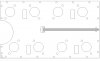
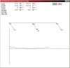
Your geometry was relativly easy to sort out. The two links are just about of equal length, r3 and r6 at 87.47 and 87.54mm.

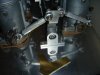
The central shaft starts at +34 degrees (from vertical, +ve being clock-wise, viewed from the back of the engine) and runs through to -34 degrees

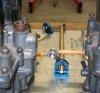
The webers rotate through 72 degrees starting at 36 degrees (standard weber 72 degree full travel).

The maximum difference of the two weber arms is 0.0188 degrees.

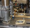
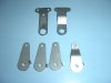
So you can use the original weber arms, and because your central shaft arm length is nearly the same as the webers there is very little error.

Remember that this is NOT allowing for any tweeks of the weber arms for tuning and idle speed, but with your set-up the weber starting angles are not to critical.

If you do stick with the original weber arms watch out for where you put the throttle cable, originals had a canted arm to give space to feed the throttle cable in.

Interesting to note that your lateral weber spacing is different to mine.

Hope this helps.

Andy
 

Attachments

  • link01.jpg
    link01.jpg
    17.2 KB · Views: 248
These are the correct carb arms for the 289 gt40 not to be confused with a 289 cobra set up. I can sell these now before they are plated and I get complete sets done if you need them.
 

Attachments

  • E & F Linkage 2.jpg
    E & F Linkage 2.jpg
    29.3 KB · Views: 269

Doc Watson

Lifetime Supporter
Nice Jay.....very nice.....

I could have saved myself a heap of time relearning how to use a needle file if I knew you were making these......

Andy
 
Back
Top