Fuel System Layout?

I am about to have a pair of aluminium tanks made up for my P4 replica, which promted this question for you more knowledable blokes out there.

The old fuel system had both tanks feeding to a small resvoir which then fed the single fuel pump and I had a single fuel level guage in the dash. Would I be right to assume that in those circumstances, the tanks both drain evenly?

Would it be worth considering doing things differently?

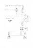
If anyone has a diagram of their fuel system layout that I could study before I commit to a plan, I would be most grateful.

TIA
Mark
 
Hi Mark -

Good to see the P4 is progressing.

There are many ways to achieve a reliable supply to the motor, but a deciding factor will also be whether it's fuel injected, or carb. The inj route requiring a return of fuel also.

For carb motors, it's quite possible to feed with a pump from each tank and also retain a single fuel gauge by having its input fed according to which tank fuel is being drawn from.

Fuel injection is a different game altogether and assuming your tanks are long and shallow, will normally require the use of a swirl pot to provide a good, uninterrupted supply of fuel to the HP pump, esp when cornering or when braking on long straights.

Another consideration is whether there is a balance pipe between the two tanks, if there is then they will drain equally'ish but a low fuel condition can become a problem made worse by them being joined.

Drop me a mail or call me if you prefer and I'll help where I can.
 
Mark this is a setup I have used with success.
EFI.

The tank in the center is your surge tank.
The 2 hoses from the top of surge going back to main tanks are bleed of's,theses must be high on both tanks.
The reg is just after the main pump going back to the surge so as not to heat the surge fuel.
I did my cross over in 5/8 id.

Jim
 

Attachments

  • PUMP.jpg
    PUMP.jpg
    17.5 KB · Views: 520
Last edited:

Peter Delaney

GT40s Supporter
Mark, here is my setup for EFI - basically the same as Jim C's, but with a changeover valve to allow use of either tank as required.

Kind Regards,

Peter D.
 

Attachments

  • Fuel System Diagram.jpg
    Fuel System Diagram.jpg
    10.3 KB · Views: 535
Thanks for those replies folks. I should have been more clear in my original post, that my engine has a 650 Holley.

I would like a setup as mentioned by Paul above,

"feed with a pump from each tank and also retain a single fuel gauge by having its input fed according to which tank fuel is being drawn from".

Paul and Frank, thanks for the offer to talk me through it. I will call during the week.

Regards
Mark
 

Terry Oxandale

Skinny Man
To add another question: Can two pumps (one for each tank) be used in parallel to feed the carb without a 3rd main pump. My concern is a scenario in which one tank goes dry, while the other is still wet. Will the wet pump continue providing effective pressure at the carb when the dry pump is pushing air into the same line feeding the carb?
 
i would advise two fuel gauges there is nothing worst than thinking the other tank is full when its not.
I put two fuel pumps into T fitting into the carb. the trick is to put one way valves just bfore the T fitting, so it doesn't pump into the other tank. When you want a lot of fuel turn both pumps on. this works extremely well with a carburator

LLoyd


LLoyd
 
Back
Top