

On my dash I have the lighted paddle switches. They are three pronged and have the light on the end of the paddle. It makes it easy to see if the switch is on or not. The switch here is basically the same switch.

I kept noticing that some of the switches would not light and some would. Since I am taking care of all the little nagging problems while the engine is out, I searched the web to see what I was doing wrong. I discovered that for them to light up, the Acc tab has to have a load on it, or rather go to the accessory that is being controlled. These switches have high amperage ratings, and can work without a relay. They just need to be fused correctly. I like relays because of the safety factor of the switches controlling high amperage devices.
I had wired the switches off the grounds of the relays. Most wiring diagrams will show switches(usually two tabs) wired that way. If it is a fan for instance it will show the ground wire from the relay to the switch, then to the frame. A second wire from the ground wire(in front of the switch) to a thermostat, giving you dual control. With lighted switches you can't because there is no load after the switch.
I really wanted the water pump and the front fans to run off a switch and a thermostat. The thermostat would serve to turn the pump on even if I forgot to flip the switch(see Chucks post on refilling at the gas station and forgetting to flip switches).
This wiring may have to be changed again when the A/C is installed in a couple of months. I also want to have the pump and fans run on for 2-3 minutes after shut down, but that's another story.
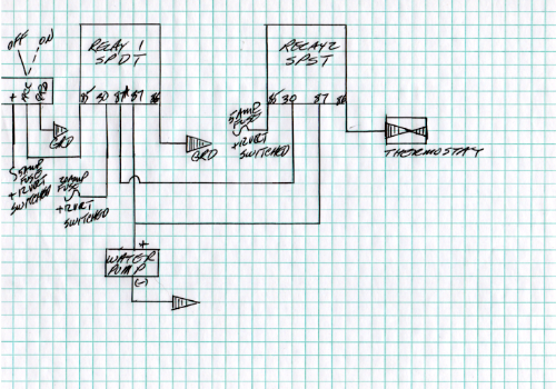
I have come up with an idea of how to wire them. Just want to see if anyone had a suggestion or thought they wouldn't work this way. All my relays ar SPDT relays(Bosh) that have a 5th wire on them. If you remove the 87A wire, it acts like a SPST.
Here is a schematic of the relays


When the coil is not energized by the switch, the flow of electricity goes from the 30 post to the 87A post. When energized it switches to the 87 post.
So I came up with the following drawing for the switch and thermostat to work together. Does anyone see anything wrong with it or have a better soution??
I kept noticing that some of the switches would not light and some would. Since I am taking care of all the little nagging problems while the engine is out, I searched the web to see what I was doing wrong. I discovered that for them to light up, the Acc tab has to have a load on it, or rather go to the accessory that is being controlled. These switches have high amperage ratings, and can work without a relay. They just need to be fused correctly. I like relays because of the safety factor of the switches controlling high amperage devices.
I had wired the switches off the grounds of the relays. Most wiring diagrams will show switches(usually two tabs) wired that way. If it is a fan for instance it will show the ground wire from the relay to the switch, then to the frame. A second wire from the ground wire(in front of the switch) to a thermostat, giving you dual control. With lighted switches you can't because there is no load after the switch.
I really wanted the water pump and the front fans to run off a switch and a thermostat. The thermostat would serve to turn the pump on even if I forgot to flip the switch(see Chucks post on refilling at the gas station and forgetting to flip switches).
This wiring may have to be changed again when the A/C is installed in a couple of months. I also want to have the pump and fans run on for 2-3 minutes after shut down, but that's another story.
I have come up with an idea of how to wire them. Just want to see if anyone had a suggestion or thought they wouldn't work this way. All my relays ar SPDT relays(Bosh) that have a 5th wire on them. If you remove the 87A wire, it acts like a SPST.
Here is a schematic of the relays
When the coil is not energized by the switch, the flow of electricity goes from the 30 post to the 87A post. When energized it switches to the 87 post.
So I came up with the following drawing for the switch and thermostat to work together. Does anyone see anything wrong with it or have a better soution??