On the Jan 2nd, I went to Houston MSR with 2155.
I found that I'm rusty as hell trying to drive after too long overseas and no track time. Managed to spin the car on street tires. My fault.
I can give you lots more excuses why if you want to hear them, but if you listen to the video, you'll hear the main reason.
")
The fuel problem I had at Texas World last time is solved thanks to Jack Houpe's excellent swirl tank design and fabrication.
Pictures of the Pantera Club (along with the Lamborghini and Ferrari club) and a couple of in car videos showing my incompetence can be found at 2012 Houston MSR
But getting to the point here.... I felt that I needed to stiffen up the swaybars. It's a race car, right? Should be a piece of cake.
Hah!
In the thread where Al was listing the differences in the Superformance cars compared to the originals, I had mentioned that the front swaybar setup is different. So I will now rant a little.
The first problem I had was one that many people have discovered. Mike Trusty said I should check and sure enough, the arms on the front swaybar were rotating on the bar. The splines weren't holding at all. Mike suggested I solve this by buying two piece sway bar clamps from Cushman and then welding the arms onto the bar, so that's what I did. Apparently this has been fixed by the factory now?
So fast forward now to last weekend when I got the car on the lift and tried to adjust the swaybar on the front to be stiffer.
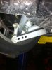
I could not do so. The link between the A-arm and the swaybar arm is too short and won't pivot enough. It looks like it should, but it won't.
The attached picture should show what I mean.
Mike Trusty suggested that the link needed to be longer. More like the original cars. So, I investigated.
Existing link has a male threaded rod end screwed into a female rod end with a jam nut.
Threads on it are 12M x 1.75.
The stud on the A-arm and the bolt hole through the sway bar arm are 12mm.
The stud is a 1.75 pitch. So is the bolt.
The length center to center is 65-70mm nominal depending on how much you screw the two ends together.
So I decide that getting a longer arm that swivels more is the answer.
I want about a 100mm long link or radius rod with what they call high misalignment bushings.
Hah! Doesn't exist. Well, not that I can find... nor that would work.
Problems I ran into are:
- Metric rod ends are rare. If you want any kind of selection, it has to be SAE. You have to use either 7/16" (too small) or 1/2" (too big). I found a place that had a selection of metric sizes, but no M12. They jumped from 10 to 14.
- High misalignment bushings would make the overall width of the rod ends too wide. The current width is 16mm. Most you can get onto the stud and still have some threads left for the nut. Max is 20mm.
- Most rod ends swivel to about 27-30 degrees, which isn't enough with the stock setup. I think the existing ones are already reaching their limit. One joint is already loosing up and should be replaced.
Someone will now, no doubt, show me exactly where to go to find what I'm talking about.:shy:
But, to carry this even further... Suppose you did find the longer rod end/link that would pivot enough.
The design of the sway bar and the link is such that you are moving the pivot point back further and further on the arm and the angle is getting bigger and bigger, so you're losing part of what you were attempting to add.
Imagine you want to stiffen it up as much as possible and move it to the last bolt hole. Imagine you have a rod end that will swivel enough and it is long enough.
The angle the link has to the arm then becomes so high that I don't think you're going to stiffen it up much anyway unless you drop the arm down a lot. But then you'll be pushing and pulling as the A-arm moves. That's not ideal, I think.
Tell me if I'm wrong, but the solution seems to be to make the arm on the sway bar arm longer so your adjustment points are more in line with the link attachment on the A-arm.
Ahhh.... but that lessens the sway bar effect so now you need a much thicker, stronger sway bar and that means you need new clamps.
I called Dennis Olthoff and he said on the racecars they are replacing the entire setup. The front swaybar is now 1 1/4" with two adjustments, rear sway bar is 1" with eight adjustments, aluminum arms and new clamps, etc.
These can be mine for $1600.
I thought I bought a car that was already designed for racing? Guess not.
But then, I'm not really racing, am I...
Comments?
What do the GT40R models have in the front from the factory? Did they fix this whole thing? Or is Dennis' solution the option everyone is using?
Seems so...
By the way, the rear swaybar is a piece of cake to adjust.
:laugh:
Whining in Magnolia,
Kirby
I found that I'm rusty as hell trying to drive after too long overseas and no track time. Managed to spin the car on street tires. My fault.
I can give you lots more excuses why if you want to hear them, but if you listen to the video, you'll hear the main reason.
The fuel problem I had at Texas World last time is solved thanks to Jack Houpe's excellent swirl tank design and fabrication.
Pictures of the Pantera Club (along with the Lamborghini and Ferrari club) and a couple of in car videos showing my incompetence can be found at 2012 Houston MSR
But getting to the point here.... I felt that I needed to stiffen up the swaybars. It's a race car, right? Should be a piece of cake.
Hah!
In the thread where Al was listing the differences in the Superformance cars compared to the originals, I had mentioned that the front swaybar setup is different. So I will now rant a little.
The first problem I had was one that many people have discovered. Mike Trusty said I should check and sure enough, the arms on the front swaybar were rotating on the bar. The splines weren't holding at all. Mike suggested I solve this by buying two piece sway bar clamps from Cushman and then welding the arms onto the bar, so that's what I did. Apparently this has been fixed by the factory now?
So fast forward now to last weekend when I got the car on the lift and tried to adjust the swaybar on the front to be stiffer.
I could not do so. The link between the A-arm and the swaybar arm is too short and won't pivot enough. It looks like it should, but it won't.
The attached picture should show what I mean.
Mike Trusty suggested that the link needed to be longer. More like the original cars. So, I investigated.
Existing link has a male threaded rod end screwed into a female rod end with a jam nut.
Threads on it are 12M x 1.75.
The stud on the A-arm and the bolt hole through the sway bar arm are 12mm.
The stud is a 1.75 pitch. So is the bolt.
The length center to center is 65-70mm nominal depending on how much you screw the two ends together.
So I decide that getting a longer arm that swivels more is the answer.
I want about a 100mm long link or radius rod with what they call high misalignment bushings.
Hah! Doesn't exist. Well, not that I can find... nor that would work.
Problems I ran into are:
- Metric rod ends are rare. If you want any kind of selection, it has to be SAE. You have to use either 7/16" (too small) or 1/2" (too big). I found a place that had a selection of metric sizes, but no M12. They jumped from 10 to 14.
- High misalignment bushings would make the overall width of the rod ends too wide. The current width is 16mm. Most you can get onto the stud and still have some threads left for the nut. Max is 20mm.
- Most rod ends swivel to about 27-30 degrees, which isn't enough with the stock setup. I think the existing ones are already reaching their limit. One joint is already loosing up and should be replaced.
Someone will now, no doubt, show me exactly where to go to find what I'm talking about.:shy:
But, to carry this even further... Suppose you did find the longer rod end/link that would pivot enough.
The design of the sway bar and the link is such that you are moving the pivot point back further and further on the arm and the angle is getting bigger and bigger, so you're losing part of what you were attempting to add.
Imagine you want to stiffen it up as much as possible and move it to the last bolt hole. Imagine you have a rod end that will swivel enough and it is long enough.
The angle the link has to the arm then becomes so high that I don't think you're going to stiffen it up much anyway unless you drop the arm down a lot. But then you'll be pushing and pulling as the A-arm moves. That's not ideal, I think.
Tell me if I'm wrong, but the solution seems to be to make the arm on the sway bar arm longer so your adjustment points are more in line with the link attachment on the A-arm.
Ahhh.... but that lessens the sway bar effect so now you need a much thicker, stronger sway bar and that means you need new clamps.
I called Dennis Olthoff and he said on the racecars they are replacing the entire setup. The front swaybar is now 1 1/4" with two adjustments, rear sway bar is 1" with eight adjustments, aluminum arms and new clamps, etc.
These can be mine for $1600.
I thought I bought a car that was already designed for racing? Guess not.
But then, I'm not really racing, am I...
Comments?
What do the GT40R models have in the front from the factory? Did they fix this whole thing? Or is Dennis' solution the option everyone is using?
Seems so...
By the way, the rear swaybar is a piece of cake to adjust.
:laugh:
Whining in Magnolia,
Kirby