Heater

Michael Fling

Supporter
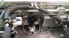
I have my compressor, condenser and evaporator in place along with having all of the AC lines run. Thanks to Allan's video. I am now on to the heater. Here is what I have:
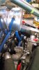
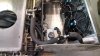
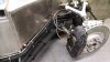
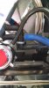
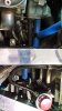
electronic 4-way heater control valve
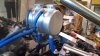
the custom surge tank with multple outlets on bottom
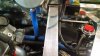
Kurt Urban Racing vapor recovery system and billet manifold

I am unclear about how to proceed. The compressor has a 5/8" and 3/4" outlet. Should the 3/4" have reducer to make everything 5/8"?

In speaking with Vintage Air, they stated that even if the 4 port system is used that the heater still needs to be controlled by the Vintage Air valve (it is system dependent)??? He said the line that feeds the heater from the 4 port is where the Vintage Air valve belongs. Is that correct?

Does the steam recover system line run to the surge tank or to the radiator?

It seems my customized surge tank has too many fitting outlets on the bottom. What should run to each outlet on the bottom of the surge tank?

I am considering having my heater lines exit from under the dash via a bulkhead fitting that is beside the bulkhead fitting for the AC exit in the front passenger wheel well area. Reasonable?

Thanks for your help…

Mike
 

PeteB

GT40s Supporter
The 4 port valve replaces the Vintage Air valve. It doesn't make any sense that you would still use the VA valve. Heck, I used the servo from the VA valve to control the defrost air.
 

Ken Roberts

Supporter
The compressor inlet and outlet sizes are referred to as #10 (low pressure) suction side and #8 (high pressure) discharge side. You do not adapt them at all (they must be configured as is)

The 4 port valve that we add at the engine is what we use with LS engines. It replaces the vacuum heater valve that is included in the Vintage Air kit. The Vintage Air servo valve that is added in the kit by Fran is to control the amount of hot air that is expelled from the heater. If you do not use the servo valve than you will be running full hot coolant through the heater core at all times unless the a/c is running. If you use the servo valve than it's door in the coolant passage will vary the amount of hot coolant that is allowed to flow through the heater core. It's use is basically a finer way of controlling how much heat the heater is putting out.

In conclusion:
1-You don't use the vacuum valve as included in the kit.

2-If you want a further way of controlling the heat output of the heater than you install the servo control heater valve.

3- If you are using a LS engine than a 4 port bypass heater valve needs to be purchased as it's not included in the kit. There are two types of 4 port bypass valves one is servo controlled and the other is vacuum controlled. This valve is installed close to the passenger side of the engine.
 
Last edited:

Ken Roberts

Supporter
The vent line runs to the surge tank. Traditionally the line enters the surge tank near the top sides where the air space is located. The line is used to help remove trapped pockets of air in the cylinder heads. Having the line enter the bottom of the surge tank isn't ideal and might not allow the trapped air bubbles to travel freely away from the cylinder heads.

You also need to plumb a line from the top of the radiator back to the top of the surge tank as well.
 
Last edited:

PeteB

GT40s Supporter
Ken,

The Vintage Air unit that comes with the kit does not have any air control at all, other than fan speed. The servo valves that come with the kit control coolant flow to the heater core (comes with a vacuum valve and a electric servo valve - use one or the other). Some of the more sophisticated (and larger) units from Vintage Air do have a heater air door, but not the one that comes with the SLC kit.
 
Last edited:

Ken Roberts

Supporter
When using a traditional small block Chevy motor you would use the vacuum valve to eliminate flow to the heater core when the A/C is running. When using a LS engine a 4 port heater valve is used to stop the flow of coolant to the core but also allow that flow to return back to the engine in a continual loop. The servo control valve would also be used in the same line to control the flow of hot coolant to the core.

The vacuum valve completely closes the flow. (used for A/C)

The servo valve acts as a gate to control how much flow you desire. (used for"heat" setting).

The electronic 4 port servo heater valve when modified for automatic operation is either open or closed. If you use the vacuum controlled 4 port valve then it is either open or closed. If you use the electronic 4 port valve without modifying it than you will not need the Vintage Air servo valve.

Lots of builders with the LS engines use the electronic 4 port servo heater valve and modify it for automatic operation. When you turn your Vintage Air to A/C setting it automatically changes the position of the valve and stops the flow to the core but also allows it to return to the engine.
 
Last edited:

Ken Roberts

Supporter
The 4 port valve replaces the Vintage Air valve. It doesn't make any sense that you would still use the VA valve. Heck, I used the servo from the VA valve to control the defrost air.

There are two different versions of the 4 port heater control valve.

1-The electronic version has a knob that will control how much coolant is allowed to flow to the heater core and how much is allowed to return without reaching the core.

2-The vacuum 4 port heater valve has no control knob and is simply fully open or fully closed.

If you use the electronic 4 port valve as it is sold to you then you can get by without using the Vintage air servo valve.

If you use the electronic 4 port valve and modify for automatic operation then it now becomes like the vacuum 4 port valve and is either open or closed (no in between settings). In this situation you would also use the Vintage Air servo to control the amount of coolant that is allowed to flow through the heater core when using the heat setting.
 

Michael Fling

Supporter
Thank you Ken- I appreciate the explanation. I can almost guarantee that I would have run my vent line to the bottom of the surge tank. One less problem avoided! I have the electronic 4 port valve that Will refers to in the build manual. Do most builders have a preference as to if it is best to modify the electronic valve or not? If it is recommended to modify it, what exactly does that entail?
 

PeteB

GT40s Supporter
If you want to be able to control the amount of heat, you need to install the control knob that comes with the four way valve and eliminate the connection to the Vintage Air mode switch. Now, the only selection on the VA mode switch that actually does anything is "A/C". I just replaced the mode switch with a push button on-off switch to turn the A/C on and off.

Here's my panel:
 

Michael Fling

Supporter
Special thanks to Allan and Ken (again) for your help. Here is a summary of what and how the heater side is going:

This is referenced when looking at the electronic heater bypass valve with the electronic part away from me and the aluminum ring at the lower half facing me. 2 ports go left (1 middle and 1 top) and 2 ports go right (1 middle and 1 bottom). The upper outlet from the heater core goes to the upper left port. The lower outlet from the heater core goes to the middle left port. The middle right port is the valve outlet that goes as the #8 line to the LS. The lower right port is the valve inlet that travels as the #10 line to the LS. I am going to place the bypass valve along with the AC/heater lines above the passenger's feet for easy access.
 

Ken Roberts

Supporter
I mentioned a #8 and #10 size due to the fact you were asking about the outlets on the compressor in your first post. I think you were meaning to say the inlet and outlet fittings for the heater on your water pump. The outlet is 5/8" and the return is 3/4".

The #8 and #10 sizes are for your a/c compressor.
 

Michael Fling

Supporter
I feel a lot more like I do now than I did a while ago. Thanks Ken… believe it or not I meant just that. Install tonight.

This is referenced when looking at the electronic heater bypass valve with the electronic part away from me and the aluminum ring at the lower half facing me. 2 ports go left (1 middle and 1 top) and 2 ports go right (1 middle and 1 bottom). The upper outlet from the heater core goes to the upper left port. The lower outlet from the heater core goes to the middle left port. The middle right port is the valve outlet that goes as the 5/8" line to the LS. The lower right port is the valve inlet that travels as the 3/4" line to the LS. I am going to place the bypass valve along with the AC/heater lines above the passenger's feet for easy access.

I may be over thinking this, but I have wondered… the line sizes should remain at 5/8" and 3/4". The ports in the bypass valve are all the same diameter. Would this not effectively constrict or affect the flow from different size lines?
 
Last edited:

Ken Roberts

Supporter
You are over thinking this Michael. Many others with SLCs and GTMs have used this 4 port valve without any problems.

Remember that part of the 4 port heater control valves job is to restrict/control flow to the heater core. If the rotary knob is set to mid position than the gate will be partially open restricting flow. My point is that you will be restricting flow anyways depending on the position of the control knob.

The vacuum controlled 4 port heater valve that I use has 5/8" and 3/4" fittings.
 
Last edited:

Michael Fling

Supporter
I am sure I am over thinking it…. but the fact is that I am still not sure how to proceed. I could not seal the 3/4" hose as it is simply too loose. Maybe I have the wrong 4 port valve… the ports on mine are all the same size. That must be my problem.

photo-4-1.jpg
 

Michael Fling

Supporter
I am used to dealing with microns. No doubt I was over thinking that if I put a reducer there that I would neglecting the earlier post that "you do not adapt them at all (they must be configured as is)". Thanks for helping me Ken. I rely on many who have stated "there are no dumb questions". Thanks for your time and expertise… I really am grateful.
 
I am sure I am over thinking it…. but the fact is that I am still not sure how to proceed. I could not seal the 3/4" hose as it is simply too loose. Maybe I have the wrong 4 port valve… the ports on mine are all the same size. That must be my problem.

photo-4-1.jpg

For clarity, for those that have the custom aluminum coolant tanks from the GB with Dave, the tanks were designed to run the 3/4" heater outlet on the engine to the 3/4" nipple on the tank. The 5/8" nipple on the tank could then be run back to the valve, or back to the 5/8" barb if you are not using a heater core.

With this design, no adapters are needed- in fact, that was the original intent of designing the tank that way. Doing the conversion at the tank is simple, and requires no adapters. But if you aren't doing the 3/4" to 5/8" conversion at the tank, you will need adaptation somewhere, as the rest of the heater circuit is 5/8".

But again, if you do have the tank, you don't need to, assuming you plumb the heater circuit as it was originally intended.
 
My 4-port valve came with what looks like a short length of thin wall rubber hose. It is designed to slip over one of the ports of the valve as an adapter so that the 3/4" ID hose will push over it and provide a snug fit.
 
For reference, here are some pictures of what my hose routing looks like with the adapter and LS engine. Many of the hoses don't have clamps on them yet.
 

Attachments

  • IMG_20140816_182916099.jpg
    IMG_20140816_182916099.jpg
    85.3 KB · Views: 241
  • IMG_20140816_182550757_HDR.jpg
    IMG_20140816_182550757_HDR.jpg
    229 KB · Views: 225
  • IMG_20140816_182603174.jpg
    IMG_20140816_182603174.jpg
    203.6 KB · Views: 205
  • IMG_20140816_182632134_HDR.jpg
    IMG_20140816_182632134_HDR.jpg
    256.1 KB · Views: 264
  • IMG_20140816_182729483.jpg
    IMG_20140816_182729483.jpg
    80.7 KB · Views: 229
  • IMG_20140816_182743332.jpg
    IMG_20140816_182743332.jpg
    81.6 KB · Views: 195
  • IMG_20140816_182800613.jpg
    IMG_20140816_182800613.jpg
    180.8 KB · Views: 200
  • IMG_20140816_182830290.jpg
    IMG_20140816_182830290.jpg
    186 KB · Views: 239
  • IMG_20140816_182530446.jpg
    IMG_20140816_182530446.jpg
    201.7 KB · Views: 249
Back
Top