First Drive

Well it finally happened; got 'er out of the garage for the first time and up and down the street.
Quite the thrill.
Dropbox - KVID1834 (1).mp4
Dropbox - KVID1835 (1).mp4

The only sad part is that in so doing I somehow fried my Koso gauge; once back in the garage, I noticed that the Koso was not registering RPM anymore (even though my android torque app was showing everything correctly). After shutting down I checked and discovered there was a blown fuse to the Koso; replaced the fuse - but now the Koso shows nothing. It doesn't do its normal start up check and no inputs are recognized - no light, turn signals, MIL light, etc.

I called Koso NA and had a brief discussion with their tech help line. They indicated the only way they thought this could happen was if the RPM signal wire to the Koso somehow received full voltage i.e 12V. I now have to buy a replacement device!!

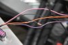
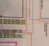
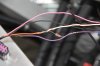
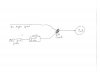
I have checked my RPM wiring and all seems well (the pull-up resistor/tach wire all as it indicated in the LS3 installation manual). I'd like to find the culprit before installing a new one.

Questions: Has anyone else experienced this? What voltage should the tach wire indicate (at the Koso connector) ignition on but engine not running? What should the range of output be for the tach signal wire?

Any help/suggestions greatly appreciated.
 
Last edited:
I haven't seen or heard of a fried Koso gauge yet, so the idea that there is a wiring issue rings true.

The RPM signal from the engine is a square wave frequency-modulated signal, not a continuous voltage, so measuring with a DMM isn't as useful or clarifying as many people think. To be sure it's right, you'll need some sort of an oscilloscope. You can get cheap USB ones on eBay and elsewhere. Here's a link from one at Amazon. It's cheap insurance against the cost of having to buy another gauge.

If the RPM signal really is the culprit, I'd check the wiring for the resistor again. It's easy to get that wrong, and as you say, you really don't want to blow another one.
 
Thanks Will; I'm pretty sure that the pull-up resistor is wired correctly and is not shorting out. I am confused as to why my tach signal at the gauge connector is reflecting 12 volts with ignition on and no engine running though?
 
you'll want to check the wiring of the GMPP controller package itself - I went through 3 that all had different major wiring issues.
 
What would I specifically look for in the GMPP harness? The tach/Koso gauge worked just fine while doing a number of engine starts in the garage; it was only when I went for my first go-kart ride that something happened - maybe just coincidence.

What tests can I run on the GMPP harness?
Thanks
 

Ken Roberts

Supporter
Check the wiring harness leads that connect to the front and rear lights. Your body is off currently. Could there be a dead short in the wires that would have connected to the front and rear body sections?

Same question for your gauge wiring in general. Was it 100% connected? Were there any other wires still left to hook up? Perhaps when you took it for a drive the unconnected wires moved and shorted to the frame.

Also...... you replaced the blown fuse but did you confirm that you are getting a complete circuit. Perhaps the wire was fried and now you have a break in the circuit. Usually the fuse will blow first but if the wire was too thin too start with it will act like a fusible link.
 
Last edited:
Re: First Drive Problem

All wires were connected and still seem to work okay after the fuse was replaced. e.g. the turn signals work with the gauge connected but no indicator shows in the Koso.

According to Koso NA, if the tach signal pushes 12V, this will fry the gauge (must not be any over-voltage protection and is probably true with other input signals)! The gauge was working properly (tach signal properly displayed) with my engine starts prior to my first go-kart.

Upon checking the output from the tach wire after the pull-up resistor, I am getting 11.8V on the tach wire. Would have got that same voltage during the engine starts. Didn't change any circuits and don't understand what changed to cause the gauge to get fried.

This seems to be all that is possible with the circuit as suggested by GM for the LS3 (pic 1) with 12V out of the ignition pin on the bulkhead connector.

Have I connected the pull-up resistor correctly (Pic 2 - orange wire from Pin L and purple from pin C; 5000 ohm resistor)? Voltage on pin C at bulkhead connector is small mVolts; after the pull-up resistor it is 11.8V? Anybody doing anything different?

Thanks for any insight into my problem.
 

Attachments

  • Pullup0000.JPG
    Pullup0000.JPG
    29.3 KB · Views: 227
  • Pullup0001.JPG
    Pullup0001.JPG
    98.1 KB · Views: 285
It appears you may have a wiring error. The bulkhead wire from "L" needs to have the resistor in series, but your picture looks like it is bridging the two wires.
 
You hit it Will.. The resister should be in line. Anyone on the forum can always buy my wiring diagram.
 

Attachments

  • IMG_8884.JPG
    IMG_8884.JPG
    179.5 KB · Views: 283
Last edited:
Okay, then maybe I'm confused; if I remove the shaded part of the circuit in the photo below, does that make it in-line/in series?
 

Attachments

  • Pullup0002.JPG
    Pullup0002.JPG
    108.5 KB · Views: 239
It looks like you have jumped the resistor across two wires rather than cutting one wire and joining it up again with the resistor in the middle.
 
like the others said, your wiring is buggered up and you fried it.

here's how you want to wire it up....the digidash uses a 1/2watt 1k ohm resistor; not sure about the koso; btw, that's a weird looking resistor.....
 

Attachments

  • wiring.jpg
    wiring.jpg
    14.1 KB · Views: 255
Alex and Rich, thanks for your responses; what I thought I had done is the same with the red wire in the diagram not currently connected to anything but available should I need ignition power at some time in the future.
I will however remove the extraneous wire to see if it helps the situation. thanks again.
 

Attachments

  • Tach.jpg
    Tach.jpg
    23.4 KB · Views: 217
are you using the isis/inifinitybox master/power cells? If so i would just use that to control on-with-ignition rather than the the gmpp wires ... much cleaner/easier that way imho.
 
Colin, the Koso has both pull up and pull down resisters built in you do not need to add anything externally. Look at pages 30 and 31 in it's manual. On page 30 you set the input pulse for your tacho. I have an LS7 and set Koso on value 2. On page 31 set the tacho impulse it can be either high or low. Mine is set on Hi because the GM ECU has a positive pulse, This means that the Koso will link to its pull down resister such that the volts on the IC pin will be Ground until a pulse is sent when the volts will be positive. When this positive pulse arrives it is what the microcontroler is looking for as a 'count it' signal.
When you put a resister in a single wire all you are doing is restricting current flow, you are not altering the voltage at all, except in extreme circomatances.
 
Back
Top