Mystery Solved

Mike Trusty

GT40s Supporter
Lifetime Supporter
The Mystery:
During the last couple of sessions at TWS if I accelerated hard the GT would pull to the left. But with aggressive driving it seemed to do fine. Could not figure out what was going on.

Well I found it Saturday by accident which probably saved an accident in the future.

This is a weak link that I noted when taking the car apart and reassembling it after I got it some years ago but didn’t do anything about it.

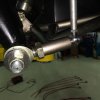
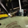
It has to do with the way that the rear sway bar link connects to the lower control arm of the rear suspension. The part that I didn’t like is that the same 8mm cap screw that connects the link to the lower control arm spherical joint is also the same 8mm bolt that keep the spherical joint in place. The joint does not screw into the lower arm but is held in place by this 8mm cap screw. Granted this allows for easy suspension adjustment but it places a lot of odd loads on this small cap screw.

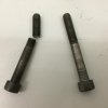
The cap screw had sheared right where it screws into the end of the joint. Because it was so long it stayed in place and actually still allowed it to do it intended job of transferring sway bar loads to the suspension. What it couldn’t do is keep the lower joint from sliding in and out of the lower control arm sleeve under hard acceleration. What is weird is that it stayed in place so long. I was simply cleaning the road grime off the suspension and hit the sway bar link with my arm the cap screw and link fell off. I could grab the bottom of the upright and move it in and out of the sleeve by hand. So under hard acceleration the joint was sliding out of the sleeve causing the left rear wheel to go excessive toe in. When power was removed it would slide back in and all was good again.

This is my fault for not replacing these low grade cap screws with better bolts as I had done with all of the other suspension bolts that I had replaced with air frame bolts. I would suggest that you replace this before any possible drama happens. There are some quality ARP blots on their way to me.
 

Attachments

  • IMG_0668.jpg
    IMG_0668.jpg
    85.7 KB · Views: 429
  • IMG_0662.jpg
    IMG_0662.jpg
    88.7 KB · Views: 426
  • IMG_0660.jpg
    IMG_0660.jpg
    73.8 KB · Views: 363
Nice save...
If you don't have the ARP number, do you remember the length so we can have the replacement ready to 'slide in'?
 

Mike Trusty

GT40s Supporter
Lifetime Supporter
Both are M8x1.25 60mm UHL(5mm shorter than what is in there to get the grip length right)
10mm 12pt wrenching and nominally rated at 180,000psi tensile. Much better than grade 8.

ARP #671-1009 for 8740 Chrome Moly Torque to 24 ft-lbs(32.5 Nm)
or
ARP #771-1009 for ARP stainless 300 Torque to 24 ft-lbs(32.5 Nm)
 

Mike Trusty

GT40s Supporter
Lifetime Supporter
The cap screw that you indicate from McMaster should be plenty strong but the text indicates that the thread length may be anywhere from 28mm to full length. That is a vague and weird description. I would not recommend a full length thread if that is what you end up with because the locator sleeve needs to be against the grip shoulder not threads. It sounds like you will get the thread length that they happen to have in stock. The bolt that is in the car from the factory has a UHL of 65mm, Thread Length of 32mm and Grip Length of 35mm. I'm a firm believer in ARP products and got what they have with the grip length as close to what is needed. If it weren't for the mystery of what thread length you will get from McMaster I'm sure it will be fine. It is a lot cheaper and you will have 23 spares. Remember that everything that is bolted to this car is also directly bolted to your butt. So where it goes you go.
 

Tim Kay

Lifetime Supporter
Fine recommendation Mike, I had the same issue simply backing out of my stall. Boy was I shocked to see this assembly so vulnerable. Along with bolt replacement I took it one step further and drilled the cap head for safety wire.
 

Terry Oxandale

Skinny Man
I don't have a horse in this race, but I'm curious as to the rear-lower-outer rod end, and how it is attached to the arm? Does it simply slide into the arm, and use the jam nut only to prevent it from moving inboard? If so, then is the M8 bolt used to prevent the rod end from moving outboard? is so, is the rod end rifle drilled and threaded to prevent the rod end from moving outboard (which makes no sense)? I'm have difficulty in understanding how the M8 bolt holds the larger rod end in the sleeve.
 
Last edited:

Mike Trusty

GT40s Supporter
Lifetime Supporter
I don't have a horse in this race, but I'm curious as to the rear-lower-outer rod end, and how it is attached to the arm? Does it simply slide into the arm, and use the jam nut only to prevent it from moving inboard?

That is correct. The rod end simply slides into a sleeve. The sleeve is NOT threaded.

If so, then is the M8 bolt used to prevent the rod end from moving outboard? is so, is the rod end rifle drilled and threaded to prevent the rod end from moving outboard (which makes no sense)?

That is correct.

I'm have difficulty in understanding how the M8 bolt holds the larger rod end in the sleeve.

The sleeve on the cap screw end has a smaller diameter sleeve/washer welded to the larger sleeve where the rod end resides. There is then a stepped bushing with the outer diameter the same as the smaller sleeve opening and an inner diameter of 8mm.
The purpose for this arrangement is to allow for quick adjustment of the rear toe. If the rod end was threaded into the sleeve then you need to disassemble the lower suspension, guess at the adjustment and reassemble and probably get to do it again. Not very conducive to quick adjustments at the track. I think the problem is two fold. One is the apparent low quality cap screw and that I found that every bolt on the rolling chassis had been over tightened from the factory. That is why I replaced all of the major bolts with AN airframe bolts. I recognized this problem from the beginning but failed to do anything about it. My bad. I often joke about the actual gorilla that I envision they have at the factory doing the final tightening of the bolts.

It is evident that the stretch load on the cap screw isn't that much because I'm not dead or hurt. It only slid out part way when full power was applied and then went back in place. That is why it was a mystery. You can not just look at it and see the problem. The cap screw was still transferring the sway bar loads because the side load on the cap screw was holding it into the sleeve described above. It was only when I put the car on the lift and hit it in the right direction that the remainder of the cap screw slide out. The rod end was happy to set there even when driving normally.
Now that we know that "aladinsane" had the same problem I think it acceptable to consider this more than a coincident.
It is much easier to replace the cap screw now. The repair required taking the suspension apart to retrieve the threaded end of the cap screw out of the rifle drilled and threaded rod end.
 

Terry Oxandale

Skinny Man
Thanks Mike. The whole idea of that was too bizarre for me to believe...I had no idea. Very interesting that a custom rod end would be needed for these. Would it be a silly question to ask what structural degradation results from the thin wall of the upright's rod end is, being it's threaded inside and outside. I understand the vast majority of loading would be tension, and not shear, but still...

My guess is that because the toe-in was the result of strong acceleration, this then jammed the rod end's threaded shank (assuming there was very tight tolerances in the thread's OD vs the sleeve's ID) as it rod end shifted outboard and slightly forward. Very scary indeed.

I wanted to do a similar arrangement on my project, but instead use and extra-long threaded shank rod end, but I couldn't find any (jam nuts in front and back). Would anybody know where I could find these style of rod ends?. The major bearing manufacturers didn't have them listed in their catalogs when I was in that stage of the build.
 
Last edited:
You guys are going to have to help me understand this. It would seem that the cap screw is subject to some side loading as well as tensile loading. My understanding is that high strength bolts have less ductility and are susceptible to fatigue failure if loaded in bending. In designing buildings we have to make sure HS bolts are loaded only in tension, or are part of an assembly where the clamping force of the bolt over rides any lateral load. Is that what's happening here?
 

Mike Trusty

GT40s Supporter
Lifetime Supporter
Daryl:

The lateral forces of the sway bar is transmitted through the sleeves that I describe above. That is why the Grip on the bolt is important and to not have threads where it is goes through the sleeve.
There is only a localized shear at the interface between the head of the cap screw and the stepped sleeve. If it is torqued properly most of that force prevents movement in the cap screw/bolt material.
The failure appeared to be a classic torsional failure that I would expect was initiated due to over torqueing and then failed under repeated hard acceleration that caused the remaining material to yield and then fail. The stock cap screws did not appear to have rolled threads. There should be no bending moment on the bolts once torqued into place.
 
I think you chose the 60 mm over the OE 65mm because the grip (threaded section) was better matched to meet the mating threaded area? A 65mm would have extended the threads into the sleeve? Anyway 170,000 psi rating is better than 80,000 psi. Makes my butt feel better. Thanks for the detail.
 
Back
Top