Requesting Photos of Cooling System

We're connecting the radiator hoses between the SPF cooling system lines and the Roush engine. I think we have a good feel for how it's plumbed, but I sure would appreciate some pics and/or confirmation.

I'll describe what I understand:

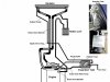
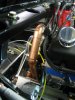
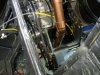
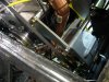
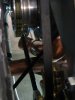
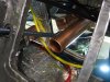
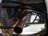
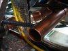
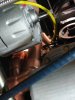
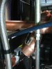
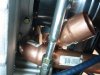
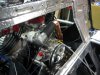
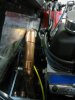
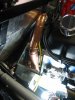
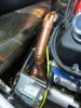
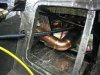
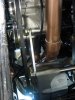
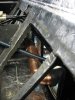
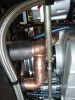
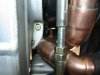
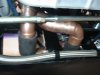
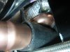
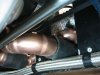
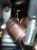
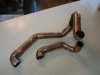
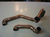
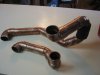
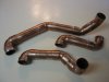
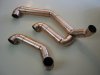
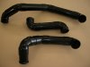
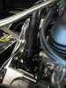
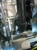
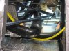
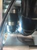
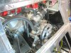
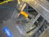
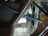
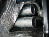
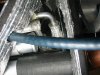
1. Thermostat neck connects to a section of rubber hose. Rubber hose connects to the ~15" section of curved stainless tube (supplied by SPF) which goes down the port side of the engine. The stainless tube connects to the upper hose just in front of the firewall.

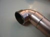
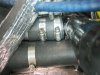
2. The water pump inlet is connected to a ~90 deg rubber hose. That hose must reach down to the lower hose just in front of the firewall. The two hoses are connected together with a short (~3") stainless sleeve and two clamps.

Can anyone confirm this configuration, from memory or by looking at your setup or sharing pics?

Thanks!
 

Attachments

  • Cooling System Diag1.jpg
    Cooling System Diag1.jpg
    66.9 KB · Views: 313
Tim, I have the hardest time posting photos on this forum. If you PM me your email, I can send you a bunch. I have a Rousch 403 in my MK1
 
I think I posted these already but here goes. I wouldn't use any of the parts you got from SPF. I made mine from copper tubing.

I drilled a small hole near the end of each tube, striped a piece of small solid core wire then threaded it through the hole and soldered it in place to keep the rubber tubing from slipping off. Lynn Miner was very nice and power coated them for me. You will also want to add a radiator petcock at the lowest point so you can drain the system if needed. I'm going to add that next time I have everything apart.

Hope this was helpful.
 

Attachments

  • IMG_4576.JPG
    IMG_4576.JPG
    321.1 KB · Views: 248
  • IMG_4574.JPG
    IMG_4574.JPG
    303 KB · Views: 243
  • IMG_4575.JPG
    IMG_4575.JPG
    308.5 KB · Views: 210
  • IMG_4577.JPG
    IMG_4577.JPG
    242.8 KB · Views: 236
  • IMG_4578.JPG
    IMG_4578.JPG
    314.4 KB · Views: 236
  • IMG_4579.JPG
    IMG_4579.JPG
    283.8 KB · Views: 186
  • IMG_4580.JPG
    IMG_4580.JPG
    283.6 KB · Views: 186
  • IMG_4581.JPG
    IMG_4581.JPG
    289.1 KB · Views: 188
  • IMG_4582.JPG
    IMG_4582.JPG
    271.5 KB · Views: 183
  • IMG_4583.JPG
    IMG_4583.JPG
    241.5 KB · Views: 193
  • IMG_4584.JPG
    IMG_4584.JPG
    302.5 KB · Views: 184
  • IMG_4585.JPG
    IMG_4585.JPG
    272 KB · Views: 186
  • IMG_4586.JPG
    IMG_4586.JPG
    264.6 KB · Views: 189
  • IMG_4588.JPG
    IMG_4588.JPG
    299.3 KB · Views: 188
  • IMG_4638.JPG
    IMG_4638.JPG
    340.3 KB · Views: 196
  • IMG_4639.JPG
    IMG_4639.JPG
    296.7 KB · Views: 156
  • IMG_4640.JPG
    IMG_4640.JPG
    297.8 KB · Views: 185
  • IMG_4641.JPG
    IMG_4641.JPG
    280.1 KB · Views: 179
  • IMG_4642.JPG
    IMG_4642.JPG
    224.7 KB · Views: 163
  • IMG_4643.JPG
    IMG_4643.JPG
    234.4 KB · Views: 169
  • IMG_4644.JPG
    IMG_4644.JPG
    247.5 KB · Views: 169
  • IMG_4645.JPG
    IMG_4645.JPG
    262.2 KB · Views: 175
  • IMG_4646-1.JPG
    IMG_4646-1.JPG
    208.4 KB · Views: 182
  • IMG_4647.JPG
    IMG_4647.JPG
    166.6 KB · Views: 167
  • IMG_4648.JPG
    IMG_4648.JPG
    169.6 KB · Views: 176
  • IMG_4649.JPG
    IMG_4649.JPG
    169.9 KB · Views: 169
  • IMG_4650.JPG
    IMG_4650.JPG
    176.6 KB · Views: 185
  • IMG_4654.JPG
    IMG_4654.JPG
    173.7 KB · Views: 172
  • IMG_4655.JPG
    IMG_4655.JPG
    166.2 KB · Views: 199
  • DSCN1405.JPG
    DSCN1405.JPG
    154.8 KB · Views: 178
  • IMG_4721.JPG
    IMG_4721.JPG
    315 KB · Views: 173
  • IMG_4723.JPG
    IMG_4723.JPG
    348.7 KB · Views: 167
  • IMG_4724.JPG
    IMG_4724.JPG
    338.4 KB · Views: 160
  • IMG_4725.JPG
    IMG_4725.JPG
    323.2 KB · Views: 165
  • IMG_4727.JPG
    IMG_4727.JPG
    294.3 KB · Views: 197
  • IMG_4728.JPG
    IMG_4728.JPG
    313.5 KB · Views: 201
BTW One of my main concerns was heat from the engine coming through the firewall. If you're going to do something about it now would be the time. If I ever have my car really apart I would fill the chassis tube that runs through the interior that holds the radiator tubes with foam insulation. The foam rubber at each end is only a few inches thick.
 

Attachments

  • IMG_3861.JPG
    IMG_3861.JPG
    137.9 KB · Views: 170
  • IMG_3846.JPG
    IMG_3846.JPG
    300.6 KB · Views: 184
  • IMG_3847.JPG
    IMG_3847.JPG
    377.2 KB · Views: 167
  • IMG_3862.JPG
    IMG_3862.JPG
    120.5 KB · Views: 201
  • IMG_3866.JPG
    IMG_3866.JPG
    116.8 KB · Views: 169
  • IMG_3871.JPG
    IMG_3871.JPG
    294.2 KB · Views: 173
  • IMG_3881.JPG
    IMG_3881.JPG
    155.4 KB · Views: 191
  • IMG_4612.JPG
    IMG_4612.JPG
    303.5 KB · Views: 208
  • IMG_4614.JPG
    IMG_4614.JPG
    295.4 KB · Views: 207
  • IMG_4631.JPG
    IMG_4631.JPG
    275.3 KB · Views: 207
  • IMG_4635.JPG
    IMG_4635.JPG
    239.6 KB · Views: 152
Richard and Gus, thank you for your efforts. I finally figured it out with some help from Gates flexible hoses.

Richard, I like the idea of closing out the heat. Thank you for the tips!

Tim
 
Back
Top