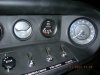
This modification changes the SPF GT40 ammeter to a voltmeter. Many of the early SPF GT40s use an ammeter that is wired incorrectly relative to the load. This error causes the meter to read off scale for nearly all conditions. When the needle is “buried”, it is of little functional use. A factory fix is in the works at the time of this post but has yet to be released. I will post it when I get it. I am of the opinion that an ammeter is of dubious value anyway. It only shows what the load is on the electrical system. It gives no indication what the condition of the battery is or that of the alternator. On the other hand, a voltmeter will tell you if the alternator is in fact charging the battery and what the voltage of the battery is.
A period accurate Smiths voltmeter is available from APT Instruments 952-881-7095 for about $60. Part number BV2220-00B is black face, black bezel like the other Smiths gages in the car.
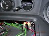
Installation is one of the easier mods you can do. Remove the six screws holding the center switch panel in place. Remove the two plastic knurled nuts that hold the meter support bracket on the back side of the ammeter. Remove the two spade lugs on the large red wires from the back of the ammeter and remove the light socket.
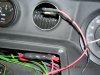
Next, cut the spade lugs off the wires and solder them together along with a 12 inch length of 14-16 gage red wire. Put shrink tubing over the wires BEFORE this soldering operation then heat the tubing after all the wires are connected. An alternate way to connect the wires is to use a butt connector. This is OK if you get a good solid connection but if you don't, you will have reliability problems making the car run because the two ammeter wires are the primary wires from the alternator and effect the ignition switch and other circuits. I used both a butt connector and soldered it.
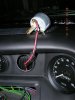
Also run another length of wire (black) and wire tie it to the red wire. This black wire can go to a common ground point under the dash. Put female spade lugs on both the red and black wire and heat shrink them as shown.
Connect the wires to the gage with the polarity shown. The voltmeter bracket is different from the ammeter bracket in that it only uses one knurled nut instead of two. Bend the bracket to match the ammeter bracket. This is required to line everything up on the back side of the dash because of the compound angles in that location.
A period accurate Smiths voltmeter is available from APT Instruments 952-881-7095 for about $60. Part number BV2220-00B is black face, black bezel like the other Smiths gages in the car.
Installation is one of the easier mods you can do. Remove the six screws holding the center switch panel in place. Remove the two plastic knurled nuts that hold the meter support bracket on the back side of the ammeter. Remove the two spade lugs on the large red wires from the back of the ammeter and remove the light socket.
Next, cut the spade lugs off the wires and solder them together along with a 12 inch length of 14-16 gage red wire. Put shrink tubing over the wires BEFORE this soldering operation then heat the tubing after all the wires are connected. An alternate way to connect the wires is to use a butt connector. This is OK if you get a good solid connection but if you don't, you will have reliability problems making the car run because the two ammeter wires are the primary wires from the alternator and effect the ignition switch and other circuits. I used both a butt connector and soldered it.
Also run another length of wire (black) and wire tie it to the red wire. This black wire can go to a common ground point under the dash. Put female spade lugs on both the red and black wire and heat shrink them as shown.
Connect the wires to the gage with the polarity shown. The voltmeter bracket is different from the ammeter bracket in that it only uses one knurled nut instead of two. Bend the bracket to match the ammeter bracket. This is required to line everything up on the back side of the dash because of the compound angles in that location.