M6B Tragic

Terry Oxandale

Skinny Man
Thanks for the tip Russell. I'll check it out. One of the things I noticed on Udo's pieces was that he double-clipped the CV on each end of the shaft. When I had my 240Z (I fabricated some adapter plates and used 930 joints), I also did the same thing, and it worked great, but on this project I chose instead to try having no clips, and let the axle float on the splines in the CVs (bumps the stubs on each side I suppose, but thus far, no wear marks on either end). The sand racing guys use this method regularly from what I understand due to their 8" to 18"+ travel designs. After some research, and consistent responses to my concerns, I chose to mimic that set-up. The only warning I got was that the splines may overheat depending on how much travel, torque, and track conditions I had in competition (how much sliding took place on the splines under torque). I shared my suspension design with them, and my use for the car, and these seeming experts said I didn't have a thing to worry about.

So...my splines are 3" long on each end (typical aftermarket axle that comes in 1/4" increments), so that allows for a lot more travel then I would ever see (plunge is enough just by itself). So far, with over a 1000 street miles, and several track days, no issues. Oh, and they are really easy to remove! Just slide it off :)

At static ride height, I can move the axle laterally about 3/8" from stop to stop, so it should never bind, and allows me more flexibility than I'd ever need in moving the upright inboard, or especially outboard if needed for later changes to suspension/wheel parameters (longer control arms).

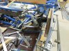
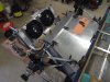
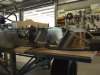
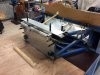
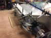
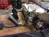
Photo from very early on in the build showing exposed splines, which are easily protected by the normal boot length.

standard.jpg
 
Last edited:
Terry, I had the company called Albins make my axles, they are the ones who made my Transaxle, you may of heard of them. Normally they only have the retaining clips on the side facing the diff and don't worry about the other end because they let it travel in towards the CV adaptor on the Hub end. I have bolt heads in there, and didn't want them mashed up, so I drew up clips on each end. The CVs are 934, size 18, 115mm and have enough plunge in them to accommodate the full suspension travel.
 
Another step forward, my mate Clayton spent a whole day with me, showing me how to sort out the position of my rack, also its length to the ball centres. Clayton dialled out the Bump steer from a shocking .410" toe in and .250" toe out on droop, to .006" toe in on bump and .003" toe in on droop. The guy's a genius in my eyes. There should be no hidden surprises with the handling. I can order my rack now.
Whilst waiting for bits, I have been doing a bit of panelling.
 

Attachments

  • IMG_1391.jpg
    IMG_1391.jpg
    186.5 KB · Views: 571
  • IMG_1392.jpg
    IMG_1392.jpg
    192.8 KB · Views: 589
  • IMG_1401.jpg
    IMG_1401.jpg
    132.3 KB · Views: 515
Here's another couple of pictures of the panelling I'm attempting.
 

Attachments

  • IMG_1396.jpg
    IMG_1396.jpg
    137.1 KB · Views: 556
  • IMG_1394.jpg
    IMG_1394.jpg
    139 KB · Views: 492
Great looking custom steering wheel. Love the wood grain look LOL
Coming along great. Makes me what to get finished with My Lotus body work. So I can get back to the chassis & susp.
 
Beautiful job Udo..

Yes, Clayton is a special bloke and definately one of the good guys..

I am always on the lookout for updates on this project. It will be a very very nice car when completed..
 
Dropped in to see Udo on our way home from a CFC cruise and took a few progress shots.
His camera has packed it in, so here’s a few for an update.
Radiator arrived during the week and he was busy working away with the front structure.
The new rack should be here soon and he’s itching to get it fitted.
Few more chassis panels made and it’s looking fantastic.

Thanks Ricky
Most people think I’m special, but not in the good way… :)

Clayton
 

Attachments

  • DSCF3524.jpg
    DSCF3524.jpg
    261.9 KB · Views: 507
  • DSCF3540.jpg
    DSCF3540.jpg
    220.7 KB · Views: 530
  • DSCF3549.jpg
    DSCF3549.jpg
    230 KB · Views: 476
  • DSCF3551.jpg
    DSCF3551.jpg
    265.8 KB · Views: 571
  • DSCF3556.jpg
    DSCF3556.jpg
    215.2 KB · Views: 518
  • DSCF3559.jpg
    DSCF3559.jpg
    248.1 KB · Views: 473
  • DSCF3530.jpg
    DSCF3530.jpg
    238.8 KB · Views: 538
  • DSCF3537.jpg
    DSCF3537.jpg
    233.5 KB · Views: 464
  • DSCF3528.jpg
    DSCF3528.jpg
    233.2 KB · Views: 493
  • DSCF3526.jpg
    DSCF3526.jpg
    271.3 KB · Views: 557

flatchat(Chris)

Supporter
Impressive workmanship there
.... in post #56 of the CVs ,the top right one is assembled correctly and the left one is wrong -- it will bind and give a horrible vibration
 
I've had a bit of a break from working on the car, and I've been visiting my son Max, who has moved to Wellington N.Z. I must catch up with some of you Kiwis on my next visit. Anyway, I have received my bespoke Titan steering rack and fitted it on the weekend. I think it looks pretty well the same as an original.
 

Attachments

  • IMG_3673.jpg
    IMG_3673.jpg
    164.4 KB · Views: 444
  • IMG_3679.jpg
    IMG_3679.jpg
    162.9 KB · Views: 529
  • IMG_3681.jpg
    IMG_3681.jpg
    168.3 KB · Views: 450
This is a fantastic build, makes me want to pull some of mine apart and re do it. What size CVs are you using? the uprights that I make can take the 127mm CVs at a pinch but I have standardized with the 108mm CVs (930). I see you are running fans, do you intend this car to be road legal??

Cheers Leon
 
Hi Leon, the CVs are 115mm size 18 ( 934 ). I have installed the fans only because where I live in Darwin it is always hot, even in the Dry Season.
I wasn't sure whether I'd need them or not, so I had the tabs welded on when they made the radiator and I've put the Fans there so I know they will clear any body work.
It will not be road legal. Mind you, it would be nice to be able to throw an M6GT body on it if I ever wanted to ( with shorter ram tubes ).:)
 
You wouldn't know the PCD of the CVs, I'm having trouble finding it on the net and Rod Brace who I'm making some uprights for wants to run those CVs.

Cheers Leon
 
Sorry Leon, the plan's a bit small, I don't know if you can enlarge it. Anyway the PCD is 94mm and the bolt holes are M10 ( I used 3/8"on the upright end, where the upright hub adaptors are USA sourced ) Hope this helps
 
Leon, STOP! Big Mistake! I've given you the wrong info, that was a Size 15, 108mm CV ( 930 ).
The correct one is a Size 18, 115mm CV ( 934 ). It has a PCD of 100mm. Still has the same M10 bolt holes. See the attachment, really sorry about that.
 

Attachments

  • 115mm CV PCD.jpg
    115mm CV PCD.jpg
    20.4 KB · Views: 428
Back
Top