Rick's RCR GT40

Rick Merz

Lifetime Supporter
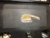
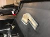
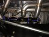
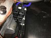
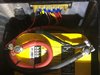
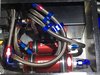
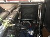
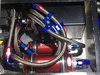
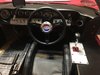
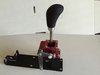
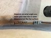
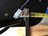
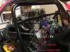
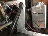
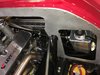
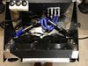
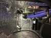
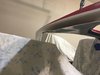
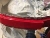
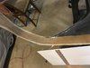
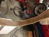
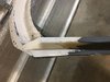
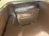
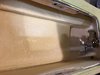
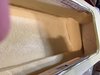
Lee, The cables on most RCR right hand drive GT40's run along the right sponsoon between the drivers seat then a hole is drilled in the rear bulkhead to route the cables. I chose to keep the extra 2" of room on the drivers side (3" where the shifter box is located if placed on the inside of the sill) and mount the shifter inside of the sponsoon next to the gas tank. I had to make a relief in the gas tank to house the shifter box. I cut a hole into the interior side of the sponsoon close to the bulkhead and routed the cables through this hole and the hole in the bulkhead to the transaxle. I had a plate made to mount the shifter box to and then mounted the plate to the sill. I probably lost 1 gallon of fuel but my comfort is worth much more. :)

John & Gary, Thanks.

Bob, 18th it is. :)

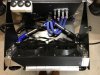
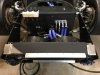
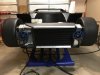
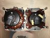
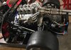
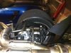
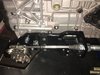
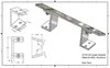
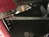
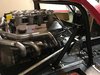
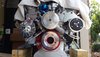
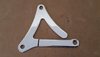
Tom, Good question, Fran would be best able to answer that question but I think the plates were bolted to the mounts to provide extra strength since more builders are opting for higher horsepower and he knew that my engine was going to be producing horsepower in the 600 to 650 range and I will be running 335/35ZR-17 Hoosier A7's on the rear.
 

Rick Merz

Lifetime Supporter
More fiberglass work...

I did not like how the water pump "bump" was done on the rear bulkhead so I ground it off and made my own. Not only does my design protrude into the interior by a 1/2" less it also allows for a/c belt clearance. Once repainted the bulkhead will look good.

I designed and made a shroud for the radiator that would house 2 Spal fans and hold the top of the a/c condenser in place. The shroud is completely sealed around all 4 edges to the radiator and even though it is only 4 layers thick and secured by 4 sheet metal screws it is very solid. I am especially pleased that I actually completed it in 1 long day (including paint)!
 

Attachments

  • IMG_0881 2028.jpg
    IMG_0881 2028.jpg
    105.1 KB · Views: 1,139
  • IMG_0882 2028.jpg
    IMG_0882 2028.jpg
    124.3 KB · Views: 1,071
  • IMG_1213 2028.jpg
    IMG_1213 2028.jpg
    154.5 KB · Views: 1,148
  • IMG_1214 2028.jpg
    IMG_1214 2028.jpg
    153.2 KB · Views: 1,130
  • IMG_1215 2028.jpg
    IMG_1215 2028.jpg
    155.5 KB · Views: 1,211

Rick Merz

Lifetime Supporter
Well a lot has been going on since I last posted. I have been working on the 40 but I also purchased 7.5 acres in Aledo Texas and I have been working on the weekends to remove trees that have grown up around the 2 acre pond. While cutting down the trees I had an accident with the chain saw (I know, you seen this one coming) and cut my little finger almost in half, good thing is that I still have it and it will heal fine the bad is that it will take 3 months for the tendon repair to heal completely. So it looks like I can not do any work with my right hand for 8 weeks, after that I can do light work for 4 weeks and then I can resume normal use of my right hand. I will take this healing time to bring my build log up to date.

Dash was completed so I installed it and started wiring the rest of the car. I installed all of the lights except the front turn signal lights since I am still looking for something that I like. I broke from tradition and went with 90mm high beam, low beam and fog lights since I prefer to have very good lights when I drive at night. If I ever sell it (maybe in 20 years when I will be 82 and no longer driving at high rates of speed) it will be quite easy to convert it back over to the original style lights if the new owner so chooses. The wiring kit supplied by RCR serves its purpose and works well. I had to purchase 1/4", 3/8", 1/2" and 3/4" convoluted tubing to protect the wires and I installed a terminal strip so that 12v could be supplied directly to fuel pump, fan, horn and head light relays as well as the key switch, alternator and 20 circuit fuse block.

I wired the Fast XIM and Sportsman XFI ecu's that will control the fuel and spark for the engine. This was somewhat a pain in the rear since the harnesses are designed for a front engine car and they had to be cut and reconfigured so that I could have a cleaner mid engine install. I takes extra time but in the end it is worth it since the wires are hidden fairly well. I placed the coils (coil on plug like modern engines) down by the oil pan so that they are out of sight as well. I like a clean engine compartment where the main focal point is the engine (and in the GT40's case) the suspension and trans-axle.
 

Attachments

  • IMG_0936.JPG
    IMG_0936.JPG
    319.7 KB · Views: 918
  • IMG_1253 1020.jpg
    IMG_1253 1020.jpg
    222.3 KB · Views: 846
  • IMG_1292 1020.jpg
    IMG_1292 1020.jpg
    218.1 KB · Views: 846
  • IMG_1514 1020.jpg
    IMG_1514 1020.jpg
    356.5 KB · Views: 884
  • IMG_1641 1020.jpg
    IMG_1641 1020.jpg
    309 KB · Views: 882
  • IMG_1642 1020.jpg
    IMG_1642 1020.jpg
    254.2 KB · Views: 827
  • IMG_1664 1020.jpg
    IMG_1664 1020.jpg
    247.3 KB · Views: 888
  • IMG_1409 1020.jpg
    IMG_1409 1020.jpg
    270.9 KB · Views: 910
  • IMG_4377.JPG
    IMG_4377.JPG
    373 KB · Views: 864
  • IMG_4403.JPG
    IMG_4403.JPG
    405.3 KB · Views: 881

Rick Merz

Lifetime Supporter
Installed the rear sway bar, I am still missing the front sway bar since October 2015, I have the other pieces for the front sway bar but not the bar. I do not think that it should take 2 years to get a sway bar but I guess that I am wrong (it must be made out of unobtainium). I had to rotate the oil cooler by 90° so that it would clear the rear deck and I added a brace but I still have to add another brace to it. I also rotated the fuel pumps so that they were horizontal which lowered all fuel componets so that a flat cover will cover them, I still have to make the cover. I replaced the RCR supplied shifter with a CNC Performance Parts shifter and transaxle adapter. I can select all gears with little effort and the shift is very smooth. I was having trouble selecting gears with the RCR supplied shifter but this may have been my fault more than the shifter's fault, I just couldn't get it adjusted perfectly. I had to make a larger plate since the shifter is wider than the RCR supplied shifter and I did not want to rework my fuel tank for a second time. At some time in the future I am going to shorten the shift lever by one inch.
 

Attachments

  • IMG_4398 1020.jpg
    IMG_4398 1020.jpg
    253.4 KB · Views: 755
  • IMG_4399.JPG
    IMG_4399.JPG
    362.1 KB · Views: 780
  • IMG_4403 1020.jpg
    IMG_4403 1020.jpg
    304.2 KB · Views: 802
  • IMG_4408 1020.jpg
    IMG_4408 1020.jpg
    235.9 KB · Views: 796
  • IMG_4453 1020.jpg
    IMG_4453 1020.jpg
    268.6 KB · Views: 855
Nice. Good progress.
Did you take any photos of the shifter before you installed it?
I would like to see it as I'm considering other shifter options also.
 

Rick Merz

Lifetime Supporter
This post is in response to Mitch's questions.

I angled the oil cooler to put the cooler parallel to the rear end fiberglass (slightly past vertical). I attached a pic of the bracket as well as a pic of the drawing for it.

I purchased the nitrogen strut, end socket caps and ball posts from McMaster Carr, order strut 9416K21 @ $22.49ea. (select 50 pound), ball socket end (for strut) 9416K79 @ $3.58ea. and ball end stud 9512K63 @ $1.79ea. I attached them to the clip with a 1"x1" aluminum angle that was bolted to the inner wheel well where it meets the rear deck and it was epoxied to the top of rear deck as well. Worth noting is that you need to stiffen the under tray since it will flex when the clip is opened. I accomplished this by bolting two 1" x 1" aluminum tubes to the underside of the under tray, the holes in the tube are counter sunk so that the under side is clean looking.
 

Attachments

  • IMG_4479 1020.jpg
    IMG_4479 1020.jpg
    238 KB · Views: 779
  • GT40 Oil Cooler Bracket Assembly 1020.jpg
    GT40 Oil Cooler Bracket Assembly 1020.jpg
    101.7 KB · Views: 738
  • IMG_4480 1020.jpg
    IMG_4480 1020.jpg
    352.4 KB · Views: 751
  • IMG_4481 1020.jpg
    IMG_4481 1020.jpg
    227.7 KB · Views: 688
  • IMG_4483 1020.jpg
    IMG_4483 1020.jpg
    203.6 KB · Views: 683
  • IMG_2151 1020.jpg
    IMG_2151 1020.jpg
    262.6 KB · Views: 703
  • IMG_4468 1020.jpg
    IMG_4468 1020.jpg
    146 KB · Views: 802

Rick Merz

Lifetime Supporter
I wish I knew, hard to get anything lately, I ordered the Hartwell latches RCR makes last year when they were $495 a set now they are $695 a set, I wonder how that is going to work out.
 

Rick Merz

Lifetime Supporter
Thanks George, uplifting comments always help to motivate us. My next post will detail how and why I built a double bulkhead and moved the roll bar to the rear 1.5" so that it will be sandwiched between the double bulk head.
 

Rick Merz

Lifetime Supporter
I decided that I did not want the roll bar inside the cockpit where it is right behind my head. To move the roll bar behind the bulkhead required grinding the weld on the horizontal brace so that I could lower it about 2", care must be taken to only cut the weld and not gouge the roll bar. I wanted to lower the brace because I wanted to position the rear window a little lower. I had to cut off the mounting pads and shorten the braces as well. With the bulkhead in place I clamped the roll bar in place with the mounting pads under the roll bar. I clamped the horizontal bar in place and checked everything for plump and level, then everything was tacked together except for the rear braces. I removed the roll bar and had it welded then I painted it, reinstalled the roll bar and fit the rear braces which had to be shortened. I determined the length by cutting the braces in half then holding the two halves next to each other while the ends were touching the roll bar mounting pads and the monocoque I marked the overlap and cut on the marks, tacked them together and had them welded, I painted them and then bolted them to the bar and car.

Fran was kind enough to supply a new bulkhead with the rear window cutout and mounting screws deleted so that I could customize it to my taste.
 

Attachments

  • IMG_2787 1020.jpg
    IMG_2787 1020.jpg
    302.7 KB · Views: 808
  • IMG_2791 1020.jpg
    IMG_2791 1020.jpg
    253.9 KB · Views: 840

Bill Kearley

Supporter
Same shifter set up I have, nice stuff, hope it works as good as it looks. My cables are in and complete and things feel a bit stiff, hope things loosen up with some use.
 

Rick Merz

Lifetime Supporter
I have only made a short drive, about 4 blocks, and it shifted perfectly. I can shift it without the car running into every gear without any problem, I could not do that with the previous shifter. I does look good but I am going to change the shift knob, just not sure to what yet.
 

Rick Merz

Lifetime Supporter
This post is in response Sean's questions.

The lines to the heater inlet and the air out from the top of the manifold go to the expansion tank. The heater inlet hose goes to the bottom of the expansion tank outlet hose barb and the air out from the manifold goes to the top inlet hose barb on the expansion tank. This will allow the air/water to be pulled from the top of the manifold and fed to the suction side of the water pump (return from the heater if connected to the heater core). This allows air to be continuously purged from the cooling system. A tee could be added to the air out from manifold hose so that a hose could be run from the radiator bleed to the top hose barb and continuously purge air from the radiator as well. I do not use this connection since once the radiator is manually bled it usually stays free of air. In the first attached picture the hoses appear to be running to the rear of the engine, I placed them that way just to keep them out of the way when I was designing the rear bulkhead, there is a front and rear bulkhead on my GT40, more about that in my next post. :)

I made my own alternator bracket, I purchased a Dodge Charger bracket and cut it apart, I also purchased an adjuster for the alternator, both from ebay. Picture was taken when I was mocking up my alternator bracket (modified RCR supplied bracket).

I routed the top heater hose to go to the left side and wrap around the air conditioner compressor and down to the bottom center of the engine then a 90° bend turns it to be inline with the center tunnel. The other radiator hose is on the lower left side and curves down with a 90° turn to line up with the center tunnel, both hoses going to the tunnel are directly on top of each other as are the tubes in the center tunnel.
 

Attachments

  • IMG_2787 1020 mark up.jpg
    IMG_2787 1020 mark up.jpg
    312.5 KB · Views: 727
  • IMG_4509 1020 Markup.jpg
    IMG_4509 1020 Markup.jpg
    266.8 KB · Views: 727
  • IMG_4512 1020.jpg
    IMG_4512 1020.jpg
    258.8 KB · Views: 695
  • 20160109_141934 1020.jpg
    20160109_141934 1020.jpg
    234.2 KB · Views: 667
  • 20160109_120551 1020.jpg
    20160109_120551 1020.jpg
    124.9 KB · Views: 699
Rick,

Two more questions...

How did you route your heater hoses? - I looked for photos but couldn't find any in your build log of the front end. Did you just tee them off of the radiator hoses in the front?

What kind of lift is it that you have?

Thanks,
Sean
 

Rick Merz

Lifetime Supporter
Sean,

I routed them through the tunnel and connected them to a bulkhead pass through. When I installed my engine I thought that it was too busy at the front of the engine so I removed the heater hose pipes that I had wrapped and I will tee off of the front radiator hoses in the future. Attached picture shows when the heater hoses were run through the tunnel, also attached a picture of the hose routing under the dash.

I have a Central Hydraulics 91315 56" lift (6,000 lbs) from Harbor Freight, VERY helpful and only $1,500. I removed the arms and built 2 x 4 and plywood ramps to get over the lift with the GT40, with the ramps you could leave the arms on but since the GT40 is flat on the bottom you don't need the arms.
 

Attachments

  • IMG_1213 1020.jpg
    IMG_1213 1020.jpg
    260 KB · Views: 692
  • IMG_1268 1020.jpg
    IMG_1268 1020.jpg
    426.4 KB · Views: 688
  • IMG_4532 1020.jpg
    IMG_4532 1020.jpg
    371 KB · Views: 741
Last edited:

Rick Merz

Lifetime Supporter
Sean,

BTW the lift weighs over 800 lbs so plan on how to move it when it's delivered. I actually used my engine hoist to get it off of the truck since it did not have a Tommy lift and sat it on two 4 wheel dollies and a friend and I pushed it up the driveway and into the garage. I then used a engine hoist to unpack it.
 

Rick Merz

Lifetime Supporter
I decided that I wanted to stiffen the spider by closing the "A" pillars with fiberglass and filling the space between the roof and inner panel with expanding foam similar to how Tom did his roof. I used 3 layers of cardboard to make the molds, the 1st layer is bent to shape then I added a 2nd layer (bent to shape) with aluminum duct tape and then I added 3rd layer (bent to shape) with aluminum tape. To finish the mold a layer of aluminun duct tape was applied to the side that will receive the fiberglass and expoxy since the cured fiberglass will not bond the the aluminum tape. This method will make a cardboard mold that will retain its 3D shape. I laid up 4 layers of fiberglass mat onto the molds, and clamped (light load as to not squeeze the resin out of the fiberglass just enough pressure to hold the molds in place) the molds to the "A" pillars. I did this work with the spider in place to ensure that it would stay in the correct shape and I was too lazy to remove the engine since I felt confident that I wouldn't make a mess :). After curing I removed the molds and removed the spider and sanded the fiberglass smooth. I added an additional 2 layers of fiberglass mat and sanded it smooth again. I bolted the spider onto the car and was able to stand on the rear area of the roof without any movement (I weigh 245 lbs). I filled the roof cavity with foam as Tom did since the foam will add structrual ridigity and it will make the interior cooler and quieter (the door tops, door window frame and outside skin have been filled as well). The doors shut with a firm solid sound now and total weight added was about 12 lbs (roof and doors).
 

Attachments

  • IMG_1933 1020.jpg
    IMG_1933 1020.jpg
    206 KB · Views: 683
  • IMG_1934 1020.jpg
    IMG_1934 1020.jpg
    256 KB · Views: 647
  • IMG_1937 1020.jpg
    IMG_1937 1020.jpg
    269.2 KB · Views: 632
  • IMG_1938 1020.jpg
    IMG_1938 1020.jpg
    323.2 KB · Views: 661
  • IMG_1973 1020.jpg
    IMG_1973 1020.jpg
    244.3 KB · Views: 625
  • IMG_1974 1020.jpg
    IMG_1974 1020.jpg
    252.8 KB · Views: 610
  • IMG_1975 1020.jpg
    IMG_1975 1020.jpg
    216.7 KB · Views: 634
  • IMG_2266 1020.jpg
    IMG_2266 1020.jpg
    193.7 KB · Views: 628
  • IMG_2284 1020.jpg
    IMG_2284 1020.jpg
    236.1 KB · Views: 629
  • IMG_2285 1020.jpg
    IMG_2285 1020.jpg
    255.4 KB · Views: 618
Last edited:
Back
Top