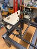
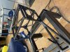
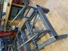
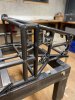
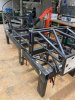
Scratch build MK IV

Randy V

Moderator-Admin
Staff member
Admin
Lifetime Supporter
Anti-dive?

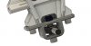
I’m not getting my head wrapped around that. It appears that the rear mount is maybe 1” higher than the front mount and the mounting holes do not share the same plane. So how will the control arm properly pivot?
 

Neil

Supporter
Randy, with spherical rod end bearings, the pivot points do not have to be in the same plane. As shown in the photo, the lower end of the rear upright will move forward as it goes up. Think anti-dive & anti-squat.
 
Watching again at your post 15th showing your cad front upright ; be aware to choice a sufficient diameter rod end in order to be sure you will have enought travel on whishbones ( 18 mm ID with hight reduced spacer is a good solution )
And why also not trying to have on top and lower bolts "double shear " arrangement (so you can go with very small bolt ?
And may be too have aprovision on upper or lower point for (double opposite threaded bung welded on the whisbone end) to help fine setting
This is a sample I did (years ago) for some UK good friend builder
This is asample
16683840_427091967631923_1034124660899641626_n.jpg
15894379_399092890431831_8565998458468268772_n.jpg
 
Last edited:
At the moment I plan with M14 rod-ends, my CAD says that gives me 158mm total travel.
I will go a bit bigger on the wheel carrier - we'll see
 
Hi
M14 will not for sure be Ok on uprights
1/ I doubt the travel will be ok ( beside you did a check :oops: )
2/ Means that in that area load will be "sustain" by 14- 1.5 mm say 12.5 real material diameter ... means really to use aerospace stiffness rod ends ( that are very very pricy )
A minimum of 16 x150 rod ends will be a safe decision
 
Hello Michael,

do you mean like this?
I use Fluro Motorsport rod ends
 

Attachments

  • Upright31.JPG
    Upright31.JPG
    53.7 KB · Views: 403
Last edited:
YEESSSSSSSSSSSSSSSSSSSSSS
Perfect !!!!
Where do you intend to locate the steering arm ?
Another "trick" I may suggest you if that arm is more or lest on top you can separate the top rodmount from the upright and join it to the arm and then do abolt arrengement onto a machined space on top of the upright ; so you could do your positive or negative set up caster without having to redo track set up ( look at the top of the front upright I posted)
Problem is ; with your kingpin angle ( very very unusual!!) it will be perhaps difficut
Apologise to go so deep on your design but have you really checked your scrubradius ??Aminimum " kingpin angle" of 7 to 9 degree is commonly used and from the view you posted seems you do not have such set up ... but again I am maybe missing something :rolleyes:

I just received Fluro rod ends today ; seems they are very good product for the price
 
This is a good solution to make the upper bearing adjustable. On my frame I have provided this in the brackets on the chassis with spacer sleeves.
Basis of my chassis geometry was the Audi R8, I have then adapted in CAD and the Susspensions Analyzer on my project.
Had a lot of support from two racing engineers friends

Here are my data:
8° spread, 6,92° caster, 42,4mm steering roll radius
Kingpin angle 10,53
Camber static 1,5°
Camber at 70mm deflected -3,1°.

Anti Dive VA = 19,5%
Anti Squat HA = 31,5%
Anti Lift HA = 35.8%
 
OK
All your datas are correct ; specially the roll radius ( that is result of your good kingpin angle)

"This is a good solution to make the upper bearing adjustable."
Yes and allow to have "thinner" solid slicepiece of aluminium than "big block" to start machining ;)
 
what do you think of this option to adjust the caster directly on the hub?
 

Attachments

  • Upright40.JPG
    Upright40.JPG
    54.8 KB · Views: 369
  • Upright39.JPG
    Upright39.JPG
    55.9 KB · Views: 369
Hi
Apologise
On that post I writed "so you could do your positive or negative set up caster"
I did a mistake speaking of ajusting the caster !!! My fault ( english terms mix up)
caster can be set up easily with wishbone location and washers or eventually with a sort or trackrod on the lower wishbone
It is the camber !!!
Your drawing could be ok if you place your idea on top and not on lower part and allow the part to move perpandicularly to the axle of the car
It's more securitive than sliding like you did
Just check at what I did on the pics
You will notice that the part bolted with shims to the upright is also the steering arm ...
So when you add or take off laser cut shims in beetween the upright and what we name on racing world the "akerman"you set up your camber and do not alter the steering toe

Porte moyeux avt nouveau assembléavec akerman réhaussé.JPG
 
Ahh now I understand :)
Thought I had overlooked something ...
Well the camber I can also simply adjust the upper Uniball outside.
All right - thanks for the clarification!
 
"Well the camber I can also simply adjust the upper Uniball outside."

Yes of course ( it's the old fashion !!!) ( doing so )
1/ You will have to lift the car ,undo the top whishbone nut ,unscrew the rod end ,etc etc
2/ You will have to redo your front toe ( modifying camber will increase or decrease toe )

Using shims is much more easy
Ok now it is your project and do not want to "hijack " more on your thread :rolleyes:
 
I don't know yet where exactly I will attach the tie rod to the hub. I still have to work out the issue in the Suspension Analyzer.
Then I'll see if I solve it that way.
Thanks!
 
Today once again a little further.
Goes slowly, but if you want to do it exactly....
 

Attachments

  • WhatsApp Image 2021-11-26 at 15.54.21.jpeg
    WhatsApp Image 2021-11-26 at 15.54.21.jpeg
    198 KB · Views: 311
  • WhatsApp Image 2021-11-26 at 15.54.20.jpeg
    WhatsApp Image 2021-11-26 at 15.54.20.jpeg
    174.6 KB · Views: 320
  • WhatsApp Image 2021-11-26 at 15.54.21 (1).jpeg
    WhatsApp Image 2021-11-26 at 15.54.21 (1).jpeg
    275.8 KB · Views: 336
This weekend I started with the trickiest part of the frame.
The position of the 4 wheel mounts to each other. Looks good so far
 

Attachments

  • IMG_0740.JPG
    IMG_0740.JPG
    546.4 KB · Views: 272
  • IMG_0743.JPG
    IMG_0743.JPG
    573.3 KB · Views: 266
  • IMG_E0743.JPG
    IMG_E0743.JPG
    268.5 KB · Views: 262
  • IMG_0742.JPG
    IMG_0742.JPG
    616.9 KB · Views: 260
  • IMG_0741.JPG
    IMG_0741.JPG
    604.8 KB · Views: 289
After 30 years of dreaming, 12 years of reading here in the forum, I can finally start to realize my dream of the MK IV.
I know it's going to be a very long race, but hey what the heck if not now then when.

For a long time I thought I wouldn't get any parts, but thanks to the forum, it still worked.

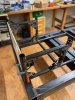
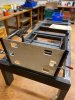
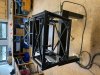
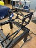
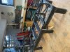
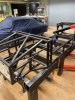
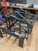
First I put some of the parts on a rack to see how they fit together.
So I can now take all the measurements I need for the tube frame.
Maybe I will bring everything with a 3D scanner into my CAD program

I hope the whole thing will be riding sometime - keep your fingers crossed for me :cool: View attachment 107417View attachment 107418View attachment 107421View attachment 107422
WOW!!
Ok so here I was thinking to myself maybe ill scratch built a Mk4 because I think it is absurdly sexy. Can you please tell me where the body came from? Did you build yourself? Bill Hughes perhaps? RCR back when they made them?
I am super jealous! This is going to be absolutely beautiful. Watching intently for updates!
 
Last edited:
Tedious but it goes forward…
 

Attachments

  • 8D253A4F-3190-4178-A038-57C81E8DE83F.jpeg
    8D253A4F-3190-4178-A038-57C81E8DE83F.jpeg
    196.7 KB · Views: 240
  • 60182415-E00F-45A4-94BC-E43F222836A7.jpeg
    60182415-E00F-45A4-94BC-E43F222836A7.jpeg
    270.9 KB · Views: 247
  • 2F2595AE-F940-404B-894E-0ED849849935.jpeg
    2F2595AE-F940-404B-894E-0ED849849935.jpeg
    321.7 KB · Views: 267
  • CAA50634-48CE-4348-9FF0-1B8714E1D801.jpeg
    CAA50634-48CE-4348-9FF0-1B8714E1D801.jpeg
    266.9 KB · Views: 254
Back
Top