S2's Build Thread

Scott

Lifetime Supporter
I had been using a piece of wood to prop my doors open, but while at Allan’s I noticed that he would slide an undersized bolt into a hole in the hinge to keep the doors open. This keeps the door opening clear and prevents the door from becoming a guillotine when you accidentally bump the wood. I’m not sure what the purpose of the hole is, but it’s not used when using door actuators. I bought two 1/4” diameter x 5” long quick-release pins from McMaster. There’s no need for anything other than round piece of metal, but I wanted to attach a lanyard (a piece of string) to keep it from getting misplaced. The pin only needs to be long enough to bridge the bolts, but I found that the extra length makes things a bit easier.

1644003289299.png

The pin holds the door open in a nearly vertical position

1644003313760.png

The pin rests on the screw heads and washers which prevents the fiberglass from being damaged.
 

Scott

Lifetime Supporter
While mounting the Y-block for the intercooler inlets, I couldn’t get the screws to lay flat. WTF? There isn’t enough of a flat spot to accommodate even a #10 socket head cap screw because they apparently used a ball end mill to machine that surface. All they needed to do was flatten it with a square end mill. I’m not talking about a separate operation, but rather a simple tool change. The piece is beautifully machined, but for $116.29 I expect better. In any event, it was simple enough to fix it with a center-cutting square end mill.

1644675750162.png

Note the radius created by the ball end mill; the taper in the “Y” results in the rear radius being worst than the front

1644675801504.png

Flat spot created with a square end mill; note the depth of the cut in the rear

The next step was to fabricate a bracket to mount the Y-block to the rear of the left cylinder head. Unfortunately, the Y-block was located over one of the cylinder head’s M10 tapped holes. To solve that, I used flathead screws and a 1/4” thick piece of aluminum to accommodate the depth required to countersink the screws. I designed the bracket to extend past the cylinder head and used Reflect-A-GOLD tape on the backside to provide a heatshield from the exhaust. The bracket was laser cut, the edges cleaned up with a belt sander, the corners broken with a deburring wheel and the surface brushed with a finishing wheel. The two tapped mounting holes for the 10-24 screws were drilled on a mill because they were too small to be reliably laser cut (the rule of thumb is that holes and interior geometry must be as least 50% the thickness of the material being cut).

1644675832417.png

Bracket ready to be mounted. Note the depth of the M10 countersunk hole in the lower right

1644675863063.png

Y-block mounted to rear of the left cylinder head

1644675899648.png

Bracket is covered with Reflect-A-GOLD to provide heat shield from #7 exhaust primary
 

Scott

Lifetime Supporter
The Shiftec Air Power Source (APS) provides compressed air to the shift servo. I designed a mounting bracket using the tab-and-slot approach with relieved corners discussed in a previous post. SendCutSend’s price point and quick turnaround is a game changer. It only cost $48.46 to have the following six different parts laser cut from 1/8” 6061, deburred and delivered within one week.

1644972239550.png

Center plate, four side plates and a backer plate to mitigate stresses applied to the center of the chassis tube

Welded aluminum tabs don’t look as nice as steel ones, so I decided to grind them. This reduces their strength, but this isn’t a structural piece and there are weld beads on the underside. If I were to remake this part, I’d keep the same number of tabs and slots because they facilitate fixturing and significantly reduce warping, but I’d only weld two of them before doing the beads on the backside. This would reduce the amount of welding and grinding.

1644972267038.png

Before grinding

1644972287823.png

After grinding

The APS is a well-engineered unit that’s designed to be quickly serviced. It mounts with two spikes that insert into rubber grommets and a single screw that mounts onto a vibration-dampening sandwich mount, all of which helps isolate the APS. I haven’t drilled any lightening holes in the large horizontal plate yet because I might mount the parking brake ECU to the underside.

1644972312023.png

The spikes slide into the grommets and the tab is bolted to the vibration-dampening sandwich mount

I’ve had challenges drilling straight holes in the past. Since the screws mount through the bracket, the 2” x 2” chassis tube and the backer plate, it’s particularly important that the drill is held perpendicular to the chassis tube. This can present challenges even when you have good access and can easily eyeball everything. In this case, the body made it impossible to line things up vertically.

To get the holes near perfect, I clamped the backer plate to the chassis tube so that I could use its laser-cut holes to index the largest drill bit that would fit. I then slid the drill guide over the bit and clamped it in place. Once a hole was drilled a screw was pushed through and tightened. A high-quality, alloy-steel drill jig costs about $25 and I highly recommend picking up a standard and/or metric one.

1644972345904.png

Backer plate and drill jig clamped to the chassis tube. Two holes already drilled and through bolted.

1644972413767.png

APS installed in lower left

I will also add a thin closeout panel under the APS after I get all of the lines run. The next step in to run the air line.
 

Scott

Lifetime Supporter
In a previous post I installed the nose hinges each of which was supported by a splitter support rod manufactured by Fully Torqued Racing (FTR). The next step was to replace the splitter support rods that are located in front of the wheels. The stock locations interfere with the intercoolers’ heat exchangers and while the rods are OK, the clevises are subpar.

I took some measurements and placed an order on FTR’s website. After a month and a half of waiting I attempted to contact them to no avail. Their Facebook site indicates that they’ve left a lot of customers hanging which is shame because they make nice stuff. D’oh! Mismatched splitter support rods would be a disaster. LOL. Fortunately, during the nose hinge project I had swapped the clevises that connect to the nose frame with ones designed for a weld tab, so I had an extra pair of FTR’s sexy pressed-pin clevises left over. All I needed to do was to fabricate the rods.

I purchased 1/2” 6061 rod and cut it to length. I used the lathe to face the ends and drill and tap the holes, all basic lathe operations. The next challenge was to figure out how to machine flats on the rod to accept a 7/16” wrench. It’s trivial to clamp the rod in a vice and machine one flat, but how do I ensure that the second flat is parallel to the first one? I thought about machining something to index the first flat to ensure that it was rotated 180 degrees. Wait a second, rotation is the operative word. I have a rotary table and, although I’ve only mounted it flat (i.e., horizontally) to the milling table, it has a flange that enables it to be mounted vertically. To ensure that the flats are parallel I simply need to machine one flat, rotate the table 180 degrees and machine the second flat.

1645572607805.png

Rotary table mounted vertically to the milling table, the first flat was just machined

1645572654595.png

Fully Torqued Racing makes high-quality stuff

FTR tapers their flats into the rod’s OD which looks nice and prevents stress risers. To replicate, I considered using a square mill to machine the flats and a ball mill to radius the edge. The challenge would be maintaining the depth of cut when changing tools. I’m sure that there is a procedure for doing this, but I found an easier solution. I purchased a 3/4" diameter, rounded-edge square end mill with a 1/8” corner-cut radius. Since the corner-cut radius is 4x the depth of the cut, a smooth taper is achieved. Since the cut depth is only 1/32” I could have easily created the flat in a single pass, but since I’m going for style points I took most of it off in the first pass and left 5 thousandths for the second pass.

1645572697677.png

Smooth taper with no stress risers

1645572723839.png

Fastening the top of the rod to the custom 4130 tube frame rather than the stock aluminum panel results in a stiffer splitter. The mounting tab was located as high as possible to maximize the support rod angle.

1645572748745.png

FTR’s pressed-pin clevis removes the need for a screw and nut which keeps things clean

1645572835818.png

The tabs are tack welded because I may need to tweak their location when I finalize the wheel well liner and the brake duct tube.
 

Scott

Lifetime Supporter
I considered mounting the transaxle thermostat to the top of the rear-chassis cross brace, but the routing of the four oil lines was messy. It eventually occurred to me to mount it to the bottom of the cross brace, which solved the routing issues, but increased the complexity of the mounting tabs. Specifically, the tabs are at an awkward angle on the tube’s radius and sunken into the small triangle which made it difficult to take accurate measurements. To solve that problem, I used diagonal cutters to keep shortening the end of a welding rod until it fit. The next challenge was to figure out how to fixture the tabs so that they would be properly spaced, aligned and planar. (i.e., not twisted or bent). Rather than fabricating two separate tabs, I designed a single piece with openings to facilitate cutting the center section out after welding was completed. I then fabricated a temporary plate to enable the fixture to be clamped to the cross brace.

1647392658903.png

Welding jig; tabs with disposable center section (front) and temporary clamping plate (rear)

1647392687084.png

Jig clamped to cross brace and ready for welding

The thermostat is a well-engineered unit from Improved Racing. I used a higher-temp version for my engine and in both cases the laser-etched side wasn’t visible. I contacted them and they laser etched the other side of both thermostats at no cost. They have great products (I also have one their oil coolers with integrated shroud, fans and isolation grommets) and excellent customer support. No affiliation, just a happy customer.

1647392722814.png

abs welded, center section removed and thermostat installed

After fabricating the oil lines, I wanted to mount two of them to prevent them from flopping around. The transaxle has a bunch of thoughtfully-designed inspection ports. Their covers seal via an O-ring and feature a tapped M5 boss in the center for mounting stuff. One of the cover plates provided a perfect location to mount a hose separator. The issue was that the hose separator was designed to be freestanding (i.e., the one piece bolts to the other) rather being mounted and it used a screw that was small than M5. The solution was easy. I used an end mill to enlarge the recess on the piece that accommodates the head of the socket head cap screw and I drilled a M5 clearance hole on the tapped piece.

1647392750445.png

Three of the inspection port covers; note the threaded boss in the center

1647392784254.png

Hose separators; stock (top) and modified (bottom); yeah the recess isn’t perfectly centered, but that’s what happens when you eyeball things rather than taking the time to do it the right way with an edge finder.

1647392813228.png

Two of the oil lines held in place via a modified hose separator mounted to an inspection port cover
 

Scott

Lifetime Supporter
1647797778256.png


There are four common ways to add female threads to a 3D-printed part:
  • Print them: This is only practical for larger threads and, depending on the print geometry, the support material may need to be removed with a tap if it’s not water soluble.
  • Tap the printed hole: This is only practical for small thread pitches unless you’re printing with a 100% fill which significantly increases cost, print time and weight. The issue is that most slicers only allow you to specify a global value for the following parameters: number of floor/roof layers, number of wall layers, and fill density percentage. Thee default settings for my printer are four layers for floors and ceilings, two layers for the walls (they can have different values) and 37% fill density and once you’re past the wall/floor/ceiling layers, you’re into the honeycomb. There might a slicer that enables you to increase the amount of structure around specific internal features (i.e., a hole), but I’m not aware of it.
  • Embed a nut: Depending on the geometry, printing may need to paused to insert the nut.
  • Install a threaded heat-set insert: Depending on the geometry, printing may need to paused to install the insert.
I haven’t found a situation on the car where printing the threads was feasible, so I will compare the other methods vs. heat-set inserts.

THREADED HEAT-SET INSERT VS. TAPPED HOLE

Pros:
  • Up to 3x stronger
  • Unlimited assembly/disassembly
  • Eliminates creep
  • Stronger resistance to torque
Cons:
  • Higher cost
  • Requires more space
  • More weight
  • Higher potential to damage part during installation
Several years ago had found an excellent article that published the results of strength testing performed on heat-set threaded inserts vs. tapped holes, but the link is now defunct. That article was the source of the above strength and torque claims.

THREADED HEAT-SET INSERT VS. EMBEDDED NUT

Pros:
  • Requires less space
  • Lighter
Cons:
  • Less strong
  • Less resistant to torque
  • Potential to damage part during installation
So far none of my parts have been structural, so the lower strength and torque resistance aren’t an issue.

INSTALLATING THREADED HEAT-SET INSERTS

image-asset.png

The inserts are available from a variety of places and McMaster has a good selection here. A tapered hole is required to accommodate the insert (the McMaster inserts have 8° taper). The first couple of times I sketched a tapered profile, created a reference-geometry axis and performed a revolved cut of the profile about the axis. I subsequently realized that I could do an extruded cut and specify a Draft — duh, that’s a lot easier, especially since a single extruded cut operation can be applied to an unlimited number of holes.

The inserts are installed by heating them with a soldering iron while gently applying pressure. Although a standard soldering iron tip can be used in some circumstances, I recommend using an installation tip which offers the following advantages:
  • The shoulder on the installation tip sits flat on the top of the insert which makes it much easier to install the insert straight (i.e., orthogonal to the part).
  • It indexes the insert which prevents the soldering iron from slipping off of the insert and melting the plastic on the soldering iron and marring the part’s surface.
  • It heats the insert more evenly which speeds up the process. Specifically, a standard soldering iron tip will only transfer heat via a small contact area at the top of the insert and it will take time for the tip to get hot enough to melt the plastic.
1647797841514.png

Soldering iron tips; standard (front), #4 (middle) and #10 rear (heat discolors the brass)

The installation tips cost ~$18 at McMaster, but I’m sure that they can be obtained for less elsewhere. Keep in mind that ruined parts can sum to that amount pretty quickly and you don’t need to use the optimal tip because a smaller than ideal version will work better than a standard tip. For example, a #10 installation tip would work fine for a 1/4” insert.

Like the holes, the inserts are tapered so you want to ensure that you orient them properly. Yeah, that’s obvious, but the taper is visually indeterminable and I’ve ruined a couple of parts by not paying attention. The knurling it typically located at the top of the taper, but if you’re not sure you can just mic both ends.

The installation/heating process seems to make it difficult to wind a screw into the insert post installation and some plastic may have been pushed forward into the hole and or into the insert. I found that running a tap through the insert from the soldering iron side solved those issues.

EXAMPLE PARTS

1647797883956.png

Tube separator for two -8 transaxle oil lines and a -4 air line for the shift servo; two 10-24 threaded heat-set inserts were used on the bottom side

1647797916321.png

End cap for the side-impact bars. It is tight enough to remain in place without a screw, but I added a heat-set insert to ensure that it wouldn’t move if bumped.
 
Great info! If you wanted to pursue the other option... I printed a mount for my ECU, only wanted to make solid the part that the ECU bolts to. This tutorial showed me how to do it.


20220119_111943.jpg


20220120_123034.jpg
 

Scott

Lifetime Supporter
Dave,

Thanks for the info. That's a great feature to have in the slicer, While I love having a cloud-based slicer integrated into my printer, my printer can't take advantage of features in a 3rd-party slicer. I sent MarkForged a link to the video and requested the feature. I had asked for the feature a long time ago, but now that it's been done elsewhere maybe they'll focus on it.

I have had many situations where I'd like to change the fill density in certain areas. However, I think I'd stick with the heat-set inserts when tension is pulling the taper into the part. If tension were pulling the taper out of the part, I expected a low number of install/remove cycles and I had that feature available, I would give thought to tapping the part.
 

Neil

Supporter
I had been using a piece of wood to prop my doors open, but while at Allan’s I noticed that he would slide an undersized bolt into a hole in the hinge to keep the doors open. This keeps the door opening clear and prevents the door from becoming a guillotine when you accidentally bump the wood. I’m not sure what the purpose of the hole is, but it’s not used when using door actuators. I bought two 1/4” diameter x 5” long quick-release pins from McMaster. There’s no need for anything other than round piece of metal, but I wanted to attach a lanyard (a piece of string) to keep it from getting misplaced. The pin only needs to be long enough to bridge the bolts, but I found that the extra length makes things a bit easier.

View attachment 120729
The pin holds the door open in a nearly vertical position

View attachment 120730
The pin rests on the screw heads and washers which prevents the fiberglass from being damaged.

Here is another option for holding open doors, etc. It's simple & inexpensive. The hold open function is automatic; to close the door, just push the spring sideways a little.
 

Attachments

  • Spring Support 4.jpg
    Spring Support 4.jpg
    113.9 KB · Views: 152
  • Spring Support.jpg
    Spring Support.jpg
    70.4 KB · Views: 143

Scott

Lifetime Supporter
In a previous post I installed the sway bars which I had purchased from Agile Automotive. They’re the same as the ones in their endurance SL-Cs that utilize cockpit-adjustable Genesis blades. Each blade rotates within a barrel via a cage bearing and a needle bearing. When the blade is horizontal it provides minimum stiffness and stiffness increases as it rotates until it reaches the vertical position, at which point it provides maximum stiffness.

1649735319138.png

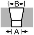
Genesis cockpit-adjustable blades; the horizontal orientation (left) provides minimum stiffness and the vertical orientation (right) provides maximum stiffness. Since the lower control arm moves straight up and down it’s intuitive that the horizontal orientation’s signifcantly smaller cross-sectional area is easier to bend.

Typically, a blade is used on one side of the sway bar and a welded arm is fabricated for the other side. I decided to opt for a symmetrical approach that utilizes two blades in which one blade rotates and the other is stationary. I took this approach for the following reasons:
  • If the bearings fail on the rotating side, I can simply flip the sway bar and invert the configuration.
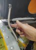
  • The stationary blade can be rotated to any position to shift the adjustment range of the rotating blade up or down. Although this has to be done while the car is stopped, you simply loosen one screw (see picture below), rotate the blade to the desired position and tighten the screw.
  • One blade is soft and the other is medium which enables me to swap them between the rotating and stationary sides of the sway bar to obtain different cockpit-adjustable ranges.
  • It looks cool… maybe I should move this to the top of the list LOL
1649735369386.png

Loosening this socket-head cap screw allows the stationary blade to be rotated to any position. This will shift the adjustment range of the rotating blade up or down

1649735419579.png

Genesis cockpit-adjustable sway bar levers

The front and rear blades are typically controlled via 10-32 push-pull cables connected to levers in the cockpit. I decided to use linear actuators for the following reasons:
  • The levers only provide five equally-spaced positions whereas the actuators provide infinite adjustability.
  • The levers are appropriate for a race car, but they crowd the cockpit of street car.
  • It’s easier to route electric wires than push-pull cables.
  • When used with position feedback, presets can be implemented (e.g., Wet, Sport, Track, Race)
It took me a long time to find the right linear actuator. I wanted a tubular form factor for fitment reasons, the correct stroke, at least an IP67 rating (i.e., waterproof for short-term submersion), excess load capacity, and position feedback. I found one that checked all of the boxes except the feedback. It had an optical encoder option, but I wanted absolute rather than incremental position feedback. To solve that problem, I purchased a motorsport-quality linear potentiometer.

The best location to mount the bracket was the nose subframe. I designed and 3D printed a bracket, but I wasn’t able to get it to clamp the tube as tightly as I wanted. The solution was a hybrid composed of two-piece stainless steel clamping shaft collars, 1/8” stainless plate and 3D-printed parts. It’s robust and light.

1649735442802.png

Stainless steel and 3D-printed parts for the front and rear brackets for the front sway bar actuator

1649735669473.png

All parts for the front sway bar actuator bracket are welded; rear bracket (left), front bracket (top) and actuator tip bracket (right)

1649735489233.png

Ready to install; 10-32 threaded rod (left), linear potentiometer (red), linear actuator (black)

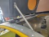
The video below provides a quick overview and demonstrates the actuator rotating the blade. Ignore the hex nuts, they’ll be replaced with nylocs at a later time.


I purchased milspec trim switches which will be mounted to the steering wheel as shown below. Upward pressure increases stiffness and downward pressure decreases stiffness. The switches will be connected to MoTeC inputs and the actuators will be driven via H-bridges so current will flow through the switches will be nominal. The mode switch in the lower right will move the sway bars to configured presets in addition applying a bunch of other settings (e.g., engine tune, gear-shift tune, percent slip, etc.).

1649735563859.png

Mock steering wheel. The top trim switch is the front sway bar and the one under it is the rear sway bar.
 
WOW

Those adjust on the fly swaybars are slick. Some of the rock racers in ultra 4 racing use a lever actuated swaybar. it allows the driver to disengage the swaybar on their machines when they leave the highspeed desert race section of the course and enter the slower technical rock sections where more wheel travel is needed.

Question for you. In a car such as yours would the racer be potentially adjusting the swaybar trim turn multiple times during a lap? And if so, would the linear actuator move quick enough? How are these adjustable swaybars used in practice during a race lap?

Are you confident that the linear actuator you are using can handle the massive compression and tension forces it will be exposed to during use? even if not actively moving the threads in the actuator will be taking a pounding.
 
Last edited:

Scott

Lifetime Supporter
Dusty,

Other than the presets, my primary use case is to not waste track sessions. Unless you have a pit crew, stopping the car, unbuckling, opening the nose and/or tail, adjusting the sway bars and buckling back up again would pretty much kill a session. The settings would have to be absolutely terrible to consider doing that, so you wait until the end of the session to adjust and there is no guarantee that you get it right. My solution allows me to optimize in 2N laps rather than N sessions.

Once you get things dialed in, there are three common reasons to change during a session/race:
  • The track gets more wet or more dry
  • The rear tires degrade
  • Fuel consumption changes balance (less of an issue in a SL-C because the fuel tank is located immediately behind the driver)
Would a driver change the sway bar settings for different corners? I’m not sure, so it would be great to hear from someone with real-world experience. The presets would make it simple for the driver to change with little distraction. My current actuator takes about 4 seconds to traverse from one extreme to the other which would be the worst case. The manufacturer offers a version that is 2.9x faster which reduces that to 1.4 seconds, but the static load rating is reduced by about 10x (that said, I think there is a huge safety margin).

With respect to the “massive” forces… I had the same concern, but the stock setup is a 10-32 push/pull cable connected to a 10-32 bolt in single shear. Apparently very little force attempts to rotate the blade. The actuator uses a trapezoidal screw which is essentially a metric Acme screw. Like Acme screws they are self-locking and will not backdrive under most conditions which eliminates the need for brakes or other holding devices to sustain loads. My guess is that I have a massive safety factor.
 

Steven Lobel

Supporter
Dusty,

Other than the presets, my primary use case is to not waste track sessions. Unless you have a pit crew, stopping the car, unbuckling, opening the nose and/or tail, adjusting the sway bars and buckling back up again would pretty much kill a session. The settings would have to be absolutely terrible to consider doing that, so you wait until the end of the session to adjust and there is no guarantee that you get it right. My solution allows me to optimize in 2N laps rather than N sessions.

Once you get things dialed in, there are three common reasons to change during a session/race:
  • The track gets more wet or more dry
  • The rear tires degrade
  • Fuel consumption changes balance (less of an issue in a SL-C because the fuel tank is located immediately behind the driver)
Would a driver change the sway bar settings for different corners? I’m not sure, so it would be great to hear from someone with real-world experience. The presets would make it simple for the driver to change with little distraction. My current actuator takes about 4 seconds to traverse from one extreme to the other which would be the worst case. The manufacturer offers a version that is 2.9x faster which reduces that to 1.4 seconds, but the static load rating is reduced by about 10x (that said, I think there is a huge safety margin).

With respect to the “massive” forces… I had the same concern, but the stock setup is a 10-32 push/pull cable connected to a 10-32 bolt in single shear. Apparently very little force attempts to rotate the blade. The actuator uses a trapezoidal screw which is essentially a metric Acme screw. Like Acme screws they are self-locking and will not backdrive under most conditions which eliminates the need for brakes or other holding devices to sustain loads. My guess is that I have a massive safety factor.
I remember seeing this as a kid. My dad ordered brochures for Cobra and never built one. I grew up and built a GT-R.
 

Scott

Lifetime Supporter
The cat-back exhaust system will be made from 3-1/2” titanium tube. Each side has a 4.6” OD round muffler that flows into two 90° tight radius elbows and a 6” x 9” oval muffler. I designed brackets to connect the mufflers and had SendCutSend laser cut them from 0.187" Grade 5 titanium. They have good pricing, but titanium isn’t cheap and four of them cost $310.72.

1651632788669.png

3D-printed tack-welding supports and titanium brackets

1651632816738.png

Mufflers and brackets being tacked. Note the 3D-printed supports under the round muffler (center bottom of picture) perfectly aligns the mufflers and prevents the round muffler from rolling.

1651632855789.png

Excellent muffler/bracket fit

1651632877652.png

Once the brackets were tacked the elbows were tacked

1651632950487.png

Left-side mufflers manually held in place

The next step is to fabricate a frame from 1/2” OD 4130 tube to support the mufflers and the bumper. Once that’s done there will be a lot of pie cuts to connect to the catalytic converter and the x-pipe.
 

Scott

Lifetime Supporter
Measure twice, cut once
DaveC, I should have mentioned that I 3D printed some mocking parts to confirm fitment before placing the order.

should be fitted with a clear body
I'm going to miss looking at some of the parts when the body is on. When fabrication is done the plan is strip everything, weld/grind the "oops" holes in the chassis, brush the entire chassis and then seal it with a clear Cerakote ceramic coating that's designed for aluminum. It's an air-dry product so I don't need to bake the chassis. I haven't tried it yet, but I have high hopes. Once that's done, I'm going to have the chassis professionally photographed.

invent a CAR sized vacuum form machine to pull a body down out of Lexan. Just like RC cars.
Mesa, I need to find some new friends who don't encourage my insanity LOL

Did you consider Inconel at all?
Colin, I discussed using Inconel on my headers with my fabricator who builds a lot of stainless and titanium exhausts. While he has experience with Inconel fabrication at an aerospace job, he's only used it once in an automotive application for a turbo manifold with really high EGTs. My headers are very complex (see pictures below); stepped, equal length, 180-degree cross under, fabricated merge collectors, custom CNC's flanges etc. Materials, CNC'd parts and prefabbed parts (i.e., the merge collectors) were a little under $5k and labor was higher (maybe a lot higher, but I didn't add labor up because that provides plausible deniability with my wife LOL). Even using icengineworks blocks, it took a lot of time to design the headers to have equal length steps/primaries, proper radial firing sequence in each merge collector, enable the spark plugs to be removed, etc.

So, 321 stainless steel headers were spendy, Inconel materials are much higher and labor would be higher as well (i.e., harder to cut, must be kept perfectly clean, etc.). My fabricator didn't want to make something as complex as my headers out Inconel and suggested that I talk with someone like GoodFabs. Keep in mind that I need to make extensive chassis modifications to get the headers to fit. I didn't call them, but we estimated that just the headers would probably run 70-80% the cost of the base kit.

The cat-back system would be less practical to build in Inconel because the tube jumps from 2.0" to 3.5" OD and I wouldn't have been able to purchase prefabricated mufflers like I was able to do in titanium.

The good news is that I can explain to my wife that I did some value engineering and didn't go with Inconel.

As you can see the headers are complex. What's not shown are the four primaries crossing under the dry-sump pan.
1651938410263.png


1651938527035.png
 
Last edited:
That makes perfect sense. I generally think of Titanium and Inconel as 'cost no object' materials; so even that category has degrees of affordability!
 
Back
Top