CAV-Getting the Horsepower to the Ground - Part II

The optimist says the glass is half full. The pessimist says the glass is half empty. The engineer says the glass is twice as big as required. The GT40 owner just wants to know if the glass is the same size as the one A.J. Foyt handed to Dan Gurney at 2:47AM during a driver change at the 1967 24 Hours of Lemans.

Admittedly even the most authentic replicas are not exact duplicates of the originals. Nevertheless our cars have all of the important functional and visual features and many of the details. All of the bodies from all of the major manufacturers now have the right proportions and dimensions. There are lots of good looking replica wheels available and without a doubt all of our interiors are absolutely right on. In the engine compartment things are a bit more free wheeling. Even in original cars, oil & transmission radiators, air ducting, electrical wiring, gas, oil & water hoses are all over the place. But there are still many key features that a replica needs to replicate (imagine that).

I will mention again that that my car was one of the last stainless steel monocoque cars made by the old Cape Advanced Vehicles (CAV) before the rights to the design went to John and Jean at AutoFutura. So my comments here apply only to the first 100 or so car made by CAV and not necessarily to cars made later.

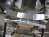
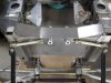
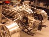
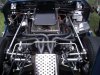
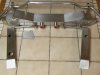
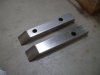
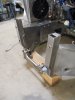
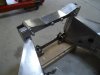
When I look inside my CAV engine compartment, all of the big pieces look right. You see the engine, transmission, headers, trailing arms, and other suspension parts in a monocoque structure as expected. But in a side by side comparison between an original GT40 and my car, one thing you notice right away is that the CAV crossmember and transmission support look out of place. From the picture you can see that these pieces are flat steel plates. One plate holds the sway bar and the other supports the ZF transaxle. I guess that these part do the job just fine but they do not have the look of the crossmember found on original GT40s.
 

Attachments

  • 64093-CAV-stockcrossmember_3.JPG
    64093-CAV-stockcrossmember_3.JPG
    118.9 KB · Views: 405
The original crossmember design is a beefy curved box section that mounts between the shocks and also supports the transmission. The sway bar is mounted to brackets that bolt to the top of the shocks absorbers. Here is a comparison picture of an original car. I wish I had one that showed the crossmember in more detail but at least the sway bar configuration is easily seen. More to come.
 

Attachments

  • 64095-GT40-1045_2.JPG
    64095-GT40-1045_2.JPG
    110.4 KB · Views: 379
Bob. As I mentioned in the other thread I thought I could see part of what would be a different cross member then stock. I have had one change in that I got rid of the first steel plate with a much better box section and mounted the sway bar under the exhaust for a better view. I still have not incorporated the trans mount to this cross member. It really ties the top of the shock towers together nicely. It can be seen at the bottom of this page.
 
One last thing. It looks at though the engine and trans are in a CAV "stock" location by the use of the bid diameter distributor. Under full bump of the rear suspension you might have the axles strike the black down tubes. In my case, I was able to use a small MSD dist., GT40 style oil pan and drop the engine ~1", trans ~3/8" and move them forward ~.75" - 1". This lowers CG, almost perfectly straightens the rear shafts and eliminates the possibility of contact of the half shafts with down tubes. Oil pan and Trans belhousing flat spot are flush with bottom of car.
 
You know you are involved with a hard core car nut when they send you pictures of prototype parts that have migrated to the kitchen counter. This is a picture of a new CAV crossmember complete with drag links, ZF transmission mount bushings, reinforcement pieces for the yoke at the end of the chassis, and miscellaneous other parts (to do a precision relocation of the upper shock absorber brackets).

Just to hold the crossmember in your hands will make a car guy smile like an idiot. It looks and feels like a part for the space program that lives in a clean room with perfect 90 degree edges, seam welding, and a very light brushed texture. I think its design is as close as one can get to an original GT40 and still fit a CAV. Admittedly this part is way over the top for installation on my car. But it does make me smile like an idiot knowing that is exactly where it is going.

It is important to point out that Gary and other have all reached this stage before me with their own designs, but I am just glad to have the opportunity to get here myself. The end game is exactly as Gary outlined in his post above and has already done on his car with obvious success and style (look at his pictures!). So any information you guys would like to contribute, like oil pan and distributor details, are certainly welcome in this post. There is not much information to discuss about building a CAV since it is assembled by the factory. But upgrades and personal preferences, now that’s a different story.
 

Attachments

  • 64120-CAV-CrossmemberUpgrade-1_4.JPG
    64120-CAV-CrossmemberUpgrade-1_4.JPG
    114.8 KB · Views: 377
Great work by the way! Looks like the lower pieces will be used to extend the chassis and then the tops will be welded on. Followed by a bolt in cross member, etc.

In the first photo of the other post I can see a heim joint on the rear of the shifter link. Looks like another upgrade? /ubbthreads/images/graemlins/smile.gif
 

Tim Kay

Lifetime Supporter
Bob,

Beautiful indeed. I'll bet that shine on the stainless came from lots of gentle caressing /ubbthreads/images/graemlins/grin.gif Send it may way and I'll caress it some more /ubbthreads/images/graemlins/grin.gif

It's a great feeling to have bits and piece here and there that, individually may not mean much to the casual viewer, but when assembled as a whole make the car a piece of art. It's all this wonderful detail that ultimately completes the look that draws people to admire and 'feel' the whole car.
 
All of the parts in this crossmember assembly are stainless steel and match the chassis. Gary is right on the mark with his analysis of how the yoke at the end of the chassis is made stronger and wider to accommodate the crossmember itself. The pieces used for the reinforcement are U-shaped channel open on one side and tapered at the ends.
 

Attachments

  • 64173-CAV-CrossmemberUpgrade-50_2.JPG
    64173-CAV-CrossmemberUpgrade-50_2.JPG
    98.2 KB · Views: 338
Like everyone involved with this forum, I enjoy working on my GT40. However, even if you prepare yourself, study with Baba Rum Raisin, achieve spiritual oneness, and regain your lost yeti psychic powers, it still takes a truly competent jack-of-all-trades to build and take care of this car. I like to think I have most of those skills but I am not a welder. Here the channel pieces are fitted to the rear yoke of the chassis. All welders will tell you that flat parts welded together naturally take on a slight bow or curve in the direction of the weld. That was the case here with my chassis. To get a nice tight fit to the yoke with no gaps I had to grind a long sweeping 1/16 inch concave curve on the back side of the channel pieces. Welders like parts with no gaps. It makes their work much easier and more likely to look really good.
 

Attachments

  • 64174-CAV-CrossmemberUpgrade-52_2.JPG
    64174-CAV-CrossmemberUpgrade-52_2.JPG
    118 KB · Views: 330
I think the addition of these supports is pretty insightful on the part of the designer because it discretely moves the support for the crossmember rearward and closer to the mounting ears on the ZF transaxle. (I know at least three people who will find that last sentence of interest.) In the mean time my parts have all been hand fitted. All I have to do is clamp them into their final positions and wait for the welder to arrive.
 

Attachments

  • 64175-CAV-CrossmemberUpgrade-54_2.JPG
    64175-CAV-CrossmemberUpgrade-54_2.JPG
    103.3 KB · Views: 342
Some of you may remember that I have asked a lot of questions on the forum this year about suspension measurements from CAV and other makes of cars. Boy you guys had real patience as I waded through that morass. Most recently Lynn and Peter get an extra nod for moral support because they came right out and agreed with me that there are some setup details, like ride height, where practical trumps theoretical. If this series of posts was a crime scene, then that post would be evidence of premeditation. The changes to my car are now all about those measurements.

The channel pieces only fit one way in one position. The crossmember (which locates the ZF) on the other hand could be positioned anywhere from 0 to 1/2 inch lower than the stock CAV position. This picture shows how the original CAV part is used to position and provide a location reference for the new crossmember.
 

Attachments

  • 64237-CAV-LocatingCrossmember_2.JPG
    64237-CAV-LocatingCrossmember_2.JPG
    112.3 KB · Views: 326
Might suggest that you lower until the trans is even with bottom of car (might run into lower cross member clearance issues without forward movement also). This should be about 3/8". Better drive shaft angle, etc.
 
A quick pencil line marked the original height and then I measured down from there 1/4 inch to locate the crossmember a bit lower than stock. Gary has suggested 3/8 inch but I think his engine is a little more forward than mine can go so I backed off the measurement. The flanges that hold the crossmember were then welded in place. For the purpose of this commemorative picture, the crossmember was bolted in and the drag links added. There is one little twist (from car 1083) that can only be done during the last stage of assembly but for now this completes the big parts needed to move the engine and transmission more forward and lower than stock.

Part I was motor mounts, Part II is crossmember, and Part III (which will not start for a few days) will add a set of full floating lower A-arms available from Ian at CAV-Canada. Sure to be a caster altering experience.
 

Attachments

  • 64286-CAV-CrossmemberUpgradewithDragLinks_2.JPG
    64286-CAV-CrossmemberUpgradewithDragLinks_2.JPG
    120.2 KB · Views: 317
The key to moving the engine forward and down was small distributor, GT40 style pan, and short water pump. I actually do not need the hump in the firewall!
 
Back
Top