CAV - Getting the Horsepower to the Ground - Part III

“Never sleep with anyone crazier than yourself”. It is one of those bits of wisdom that is meant to make you pause and consider the consequences. But at the same time it is kind of a compliment because you can imagine it’s the sort of thing Keith Richards would say to Mick Jagger (or vise versa). I am not cool enough to need a warning like that. The warnings I get are more like “don’t wear brown shoes with a blue suit”, and in the case of suspension work, “seek out lots of advice.”

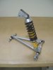
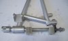
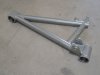
The real focus of this post arrived about 6 months ago when I received a set of full floating rear A-arms for my CAV monocoque. These upgrade parts were purchase from Ian Clark at CAV-Canada. A few posts on the forum with pictures and comments have already been made by Ian so I will not repeat that information.

I immediately did the installation, drove the car for a month and was really pleased. As crazy as it might sound, the overall affect was less. Going through corners, the car just felt more stuck to the ground with less bounce, and steering required only smaller micro adjustments. I assume the bounce through the corners was from the stock rubber bushings alternately compressing and expanding and now that movement is gone. This is not to say the ride was softer, but it was much flatter without wallowing. Although I have spent a respectable amount of time racing, this was the first time that I have had the opportunity to feel an A/B comparison. No wonder that CAV racers add full floating rod end suspensions. So now I am a convert and think that these A-arms may become the single most important change I will make.

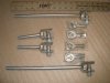
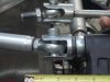
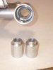
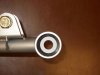
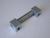
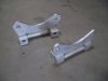
So for Part III of the project I have A-arms from CAV-Canada. I also bought a set of larger and stronger trailing arm yokes from AutoFutura. And finally from the same source as the motor mounts and cross member, I bought a reinforcement bracket that bolts to the bottom half of the rear uprights. Each of these parts does something good.

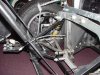
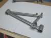
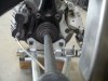
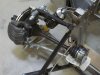
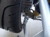
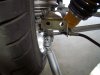
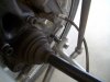
This picture shows the starting point. Fresh from shipping, this car is a little dusty but with the drive shaft removed, all the relevant early design parts can be seen. The flat steel crossmembers were previously replaced with a single stainless steel box section described in Part II. The stock lower A-arms are V shaped with rubber bushings and no cross bracing. The uprights have an external frame. The smaller trailing arms yokes can also be seen. All of these pieces will change. I will remember to not wear brown shoes and to not let the car fall.
 

Attachments

  • 64519-CAV-PriorDesign_3.JPG
    64519-CAV-PriorDesign_3.JPG
    103.8 KB · Views: 374
To keep the story in sequence I need to first mention the trailing arm yokes from AutoFutura. They fit on the top and bottom of the rear uprights. The new yokes have a much wider range of movement and are less likely to bind as suspension travel approaches the upper and lower limits of movement. I think these sorts of upgrade parts are now standard on the new cars being shipped by John and Jean.
 

Attachments

  • 64529-CAV-UpgradeYokes-1.JPG
    64529-CAV-UpgradeYokes-1.JPG
    76.2 KB · Views: 344
The difference in the original yokes and the new parts is clearly seen in the following picture. The new parts are much stronger. These parts are a bolt-on replacement to upgrade stock CAV rear suspension. However, they must have the connecting rods lengthened to use them with Ian’s A-arms (which is what I did). Alternatively, new yokes can be ordered directly from CAV-Canada with the correct length shafts.
 

Attachments

  • 64532-CAV-UpgradeYokes-2.JPG
    64532-CAV-UpgradeYokes-2.JPG
    102.5 KB · Views: 366
Gary,
Haven't talked to you in quite a while, Since Nashville a year ago if I remember. That has to be one of the sharpest suspension setup pieces I have ever seen for a GT-40. The ultimate in attention to detail. If I were scratch building, I would strongly consider it. I will have to live with my Corvette's for now.

Bill
 
Here is the A-arm from CAV-Canada. The other attached parts will be mentioned later. Ian has already presented and discussed his design on the forum so I am not stealing any of his thunder. As far as I am concerned all of the people who have gone to the trouble of designing and manufacturing low volume specialty parts, and make them available to the rest of us, deserve appreciation and recognition.

An exposed rod end is used at the rear corner of the upright to adjust toe. The other two corners have monoballs (ball joint swivel bearings) inside the round housings to allow the arm to float.
 

Attachments

  • 64590-CAV-A-Arm-Assembly_3.JPG
    64590-CAV-A-Arm-Assembly_3.JPG
    121 KB · Views: 328
The sequence of yoke, spacer, monoball, spacer, upright bracket, and rod end makes an easy bolt-on operation.
 

Attachments

  • 64592-CAV-A-Arm-Upgrade-10_3.JPG
    64592-CAV-A-Arm-Upgrade-10_3.JPG
    99.5 KB · Views: 340
The A-arms essentially fit flush with the bottom of the car. In that position the Teflon-lined monoballs and spacers are subject to much more road grime than the rod ends at the top of the upright in the engine compartment.
 

Attachments

  • 64705-CAV-A-Arm-Upgrade-11_2.JPG
    64705-CAV-A-Arm-Upgrade-11_2.JPG
    60 KB · Views: 317
To protect against road grime, I added thick neoprene washers stretched over the spacers on both sides of all the monoballs to totally seal the area but still allow flex and movements. I know some of you will protest that this doesn’t feel natural but that is the price of protection. Side seals have also been added to the rod ends on the lower trailing arms.
 

Attachments

  • 64706-CAV-A-Arm-Upgrade-14_2.JPG
    64706-CAV-A-Arm-Upgrade-14_2.JPG
    73.6 KB · Views: 323
My A-arms came from the first group of prototypes made by CAV-Canada. I understand that some dimensions on the current pieces have been refined for better fit. One substantial change that I did make on my A-arms was to relocate the lower shock absorber bracket. This picture shows the original bracket location inset from the upright attachment point.
 

Attachments

  • 64733-CAV-A-Arm-Upgrade-15_2.JPG
    64733-CAV-A-Arm-Upgrade-15_2.JPG
    63.2 KB · Views: 344
By comparison you can see that the shock bracket has been moved so the line of force is through the attachment point and directly over the strut. The relocation also accomplished two other benefits for my car. First, moving the bracket slightly to the rear eliminated crowding between the shock absorber and the emergency brake. Second, moving the bracket out to the end of the A-arm better positioned the stroke of the shock absorber into the center of its working range (more on this later).
 

Attachments

  • 64734-CAV-A-Arm-Upgrade-16_2.JPG
    64734-CAV-A-Arm-Upgrade-16_2.JPG
    81.6 KB · Views: 336
Looks great. Two comments. I bet cutting those snap ring grooves is not fun (meaning I have not done it but would wonder how). Second I think moving the lower shock mount outboard puts less bending on the lower bracket bolts into the upright (good thing).
 
In original CAV configuration, the lower A-arms attaches to the upright via an external rectangular shaped steel frame as shown in the first picture at the start of this post. Ian recommended removing the upper part of the steel frame to leave just the lower end when using his A-arms (see following picture). The rationale is that since the new A-arms incorporate a rod end for toe adjustment, there is no need to use shims. Therefore there is no need for the top half of the steel frame since the bottom is now always bolted on flush and flat.
 

Attachments

  • 64757-CAV-UprightBrace-1_2.JPG
    64757-CAV-UprightBrace-1_2.JPG
    62.1 KB · Views: 336
As luck would have it, the same designer that made the motor mounts and crossmember had also independently eliminated the upper frame but replaced the structure with a simple flange. Here the flanges have been welded on and the parts silver chromate plated.
 

Attachments

  • 64758-CAV-UprightBrace-2.JPG
    64758-CAV-UprightBrace-2.JPG
    72.9 KB · Views: 337
The new flange piece wraps half way up around the drive shaft. The modified assembly attach with 4 bolts, instead of 2, to spread the force from the A-arms evenly over the entire lower half of the upright. I think it is a perfect companion piece to use with the parts from CAV-Canada. I always hedge my bets.
 

Attachments

  • 64759-CAV-A-Arm-Upgrade-17_2.JPG
    64759-CAV-A-Arm-Upgrade-17_2.JPG
    86.7 KB · Views: 311
This picture is a different view of the A-arm assembly with the shock absorber just set in place. The upper shock mount is still loose and not attached to the chassis. All the rest of the suspension pieces, including the trailing arms and wheels were then attached and checked for correct fit and clearance.
 

Attachments

  • 64823-CAV-A-Arm-Upgrade-18_2.JPG
    64823-CAV-A-Arm-Upgrade-18_2.JPG
    104.2 KB · Views: 356
Details, details. My car was the first car with 17 x 11 inch wide wheels to use the new A-arm design. Everything fit with room to spare on the 15 x 10 inch wheels used by Ian, but my wheels were inset so far that the inside edge of the wheels touched the modified trailing arm yokes.
 

Attachments

  • 64824-CAV-A-Arm-Upgrade-19_2.JPG
    64824-CAV-A-Arm-Upgrade-19_2.JPG
    87.7 KB · Views: 349
The interference was easily fixed by shortening the spacer between the monoball and the yoke on both sides of the car. This picture is from the first installation of the A-arms 6 months ago when I actually shortened the spacer more than necessary. During this installation a new spacer was made with 1/8 more length for a perfect fit.
 

Attachments

  • 64825-CAV-A-Arm-Upgrade-20_2.JPG
    64825-CAV-A-Arm-Upgrade-20_2.JPG
    84.1 KB · Views: 333
One other detail to mention is the length of the shaft on the rod end used to set toe. Even with a thin jam nut on the end of the shaft, and depending on the specifics of the suspension settings, there may not be enough thread length to go all the way through the last nut. Again, there is an easy correction just by replacing the 1/2 bore 1/2-20 rod end with a 1/2 bore 5/8-18 part. The head of the 5/8 inch part is slightly longer and the shaft is also slightly longer giving 1/4 inch more usable thread.

For sure this is an easy way to set toe-in. Instead of removing the stud or shaft through the rod end and then screwing the entire rod end in and out in 1/2 turn steps, the CAV-Canada method only requires the nuts to be loosened reset, and retightened. In addition the adjustments can be made in infinitely fine increments and not just 1/2 turn steps. All I need now to finish the toe adjustment is to find jam nuts that are pre-drilled for safety wire. If anyone can tell me a source for these, it would be appreciated.
 

Attachments

  • 64899-CAV-A-Arm-Upgrade-21_2.JPG
    64899-CAV-A-Arm-Upgrade-21_2.JPG
    103.7 KB · Views: 339
Back
Top