CAV - Getting the Horsepower to the Ground – Part IV

Previous parts of this unintended epic post were about the little adjustments needed to install upgraded motor mounts, crossmember, trailing arm yokes, and A-arms from three different sources. These were all ready made parts.

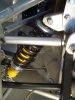
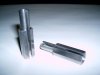
Part IV here will be about determining the best placement for new upper shock absorber brackets from AutoFutura and adding coil spring caps from mystery source number one. Just like the other parts installed, these are all early prototypes. After searching the forum for helpful suggestions I noted that this will be the first public bracket attempt since the group effort started by Mark Worthington for his RF40 last year.

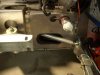
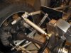
Besides the information I have been given here on the forum, I have also gone direct to the shock absorber manufacturers to understand their intentions and the capabilities of my stock CAV shocks at full extension and at full compression. I am changing the upper shock absorber bracket location on my car so that I can set: the amount of suspension rise and drop, the adjustment range of ride height, and the working range of shock absorber stroke.

In Parts I, II, and III, my attention to smaller details took a few of you by surprise and I received a number of direct email comments and a few suggestions. One was especially noteworthy and I thought totally captured the essence of my posts. It was suggested that:

“For results that can be the finest, it is our advising that
clarification is needed for motor mounts and crossmember.
Never to hold these bolts two times !!! Except the battery.
Next taking the earth section may cause a large occurrence!
However. If this is not a trouble,
such rotation is a very maintenance action,
as a kindly viewpoint from Drawing B.”

Good point, well said. I immediately invited the sender to join me as a co-author.

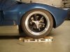
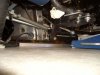
Now to work…. With 25.7 inch tall tires the space over the tire in the wheel well is too big. In this picture the car is set to a typical 5 1/2 inches of rear ground clearance. With the stock shock absorber location, I had about 1 inch of bump travel on the shock before touching the bump stops. However, if I lowered the car any more, I would also reduce the available travel on the shock by a proportional amount. For example, (ignoring shock angle and ratio components), if I lowered the car to 5 inches I would reduce shock travel to 1/2 inch. If I lowered to 4 1/2 inches I would end up riding on the bump stops. I concluded that if I wanted to lower the rear of the car then I would need to raise the upper shock bracket to regain a reasonable amount of shock travel before touching the bump stops. Others have also come to this same conclusion.
 

Attachments

  • 65042-CAVRearTooHigh-3_2.JPG
    65042-CAVRearTooHigh-3_2.JPG
    104.1 KB · Views: 434
Bob,
Let me ask at this point one question. Are your shocks stamped with a G66 or G67 or a set of each?

I am planning on shock dyno testing mine this week at a range of settings for all four shocks and will post graphs when I am finished.
 
Great Gary,

That would be very interesting information to know and I do appreciate your suggestions. My car came with yellow rear shocks, black springs, and the following markings:

SPAX M73 (on top spring cap)
SPAX 23 (on side decal)
G 6 6 A P C 0 3 (stamped in base)

All I intend to do in this phase is locate my top shock absorber brackets. When I get to suspension alignment and bump steer adjustments I am sure to also need your help. I just have to believe that most CAV cars will use the same basic modifications to minimize and fine tune bump steer. I think Mark LeVea also has some CAV specific experience with bump steer.

Bob
 

Ross Nicol

GT40s Supporter
Bob I reckon you've got a damn good handle on what your doing.Raising the top shock mount to allow for the same amount of lowering is the sort of logic I'm comfortable with.However you do sit and wonder sometimes if the manufacturer set the ride height with shock position and travel in mind.I suppose you know this but the cone shaped bump stops are not used as final crash buffers today, but quite an effective rising rate spring as you get near bump.Carroll Smith has a good explanation in one of his books.Keep up the good work and the practical thinking.
Ross
 
I found a site that has a price list showing that G67AP is the shock for "GT Developments R" and G66AP is the shock for "GT Developments F". CAV #16 came with G66 front and rear. I wonder what the difference in length might be for the G67AP? Anyone have these shocks?
 
I wanted to reduce the amount of space between the top of the tire and the wheel well. The only way I know to do this is to lower the car which I did in small increments. When I got down to 4 1/4 inches of rear ride height clearance, the tire was at least centered in the wheel well with equal space from tire to fender on the front, back, and top. I though any lower and the car would not be practical to drive on the street so I settled on the equalized space around the tire and 4 1/4 inch of rear ground clearance. (I have another car with less than 4 inches of clearance and it seldom has a problem on the street so 4 1/4 inches seemed reasonable.) So this is my starting point, mostly based on a cosmetic decision about what looks right and a guess at reasonable minimal road clearance. Now I need to find out where the shock must be attached to produce this result.
 

Attachments

  • 65068-CAVRearSetLower_2.JPG
    65068-CAVRearSetLower_2.JPG
    95.6 KB · Views: 460
What comes next could get real complicated. First, we need to attach 74 self-adhesive reflective measurement points to all the critical locations on a bare chassis tub so that we can use a three dimensional ultra violet laser interferometer (with 6-axis degrees of freedoms) to capture the pivot points and then port that data base into a solid modeling program that can run a real time integrated suspension frequency simulation.

Or, on the other hand, I could just measure the length of the shock and mark the distance. I think I will do option 2. (After all, I am simply adjusting the positioning of the shock’s working range to where it would have been if I had used taller tires.)

The shocks are 14 inches in length when fully extended. There is 2 1/2 inches of stroke before touching the bump stops. I want the shocks to routinely function within the 2 1/2 inch range of stroke and not routinely touch the bump stops. I will divide the 2 1/2 inches of stroke into 1 inch of drop and 1 1/2 inches of rise. This means the total length of the shock would be 14 - 1 = 13 inches when the car is stationary and carrying the static weight of the car with 1 inch available to extend for drop and 1 1/2 inches available to compress for rise. So, 13 inches is first number needed.

The second number is the compressed length of the shock absorber including compression of the bump stops. In full compression the shock is expected to stop the rise of the suspension and prevent the car from bottoming out. The full compressed length is between 10 1/2 inches and 11 inches depending on how much force is used to compress the rubber bump stops. I am going to use the 11 inch number but will check the 10 1/2 inch position just the same.

To make thing easier, I made two gauges, one 11 inches long and another 13 inches long that can be bolted directly to the bottom shock mount to accurately set these lengths. An aluminum plate was bolted to the chassis. With the car sitting at the desired ride height (and ground clearance) I scored an arc with the 13 inch gauge that represents top and bottom of the bolt hole where top of the shock must be located.
 

Attachments

  • 65197-Set13_2.JPG
    65197-Set13_2.JPG
    132.2 KB · Views: 488

Ian Clark

Supporter
Hi Bob,

Wow, 6 axis laser interfermoter! Guess the NASA boys noticed you smuggling the stuff out:)

Very impressive work for sure. Also speaks to the implications of changing tire sizes. Would be nice if there was a Z rated tire to fit front and rear in original diameters (24 & 26"). Luckily I still have my rose coloured glasses...

Good luck with the R&D, nice to see someone else at least as afflicted as me. Anything I can do, just give me a call.
 
Hi Bob. Thanks again. Can you take a shot looking directly from behind the car with your scribe marked plate in view? I will compare to stock location. I was wondering if the adjustment for stock setups could be to shorten the stock ears and re-drill holes? I know in your case you have the well crafted cross member, etc.
 
Ian, -- Thanks, any help is appreciated. Have you come up with a way to extent the emergency brake cables to accomodate your A-arms?

Gary -- You are absolutely right and that is what I did during my initial testing. Here is a picture of the shortened bracket. This avoids welding but also tips the shock to the inside.
 

Attachments

  • 65307-Shortenedbracket_2.JPG
    65307-Shortenedbracket_2.JPG
    102.1 KB · Views: 426
Another way to do the same thing would be to just cut off the original bracket, trim the end at a different angle and weld it on level instead of angled down. This at least preserves the original shock angle. The stainless steel crossmember I added is specifically designed to fit that exact change as shown here. (This picture from the designer during his prototype work. Damm this is still a pretty piece!!)
 

Attachments

  • 65308-SS-Crosmember_2.JPG
    65308-SS-Crosmember_2.JPG
    144.5 KB · Views: 452
Back to the project.....With the car still at the desired ride height, I used a floor jack to lifted the rear suspension as high as it would go to determine the maximum rise that could be allowed and not have the tire touch the inside of the wheel well and still have sufficient clearance for all the suspension parts. With the suspension a full rise the distance from the bottom shock mount to the proposed upper shock mount must now be 11 inches or less to insure the shock, springs, and bump stops will be compressed enough to stop the suspension from going higher and causing damage. (this picture with floor jack removed and tire shimmed up)
 

Attachments

  • 65310-setmaxwheelrise_2.JPG
    65310-setmaxwheelrise_2.JPG
    95.6 KB · Views: 431
So, the suspension is now blocked up as shown in the previous picture. When I measured with the 11 inch gauge it was above the score marks to indicate the shock would be more compressed than 11 inches if mounted at the score marks. That is good. I swapped in a 10 1/2 inch gauge and it was perfectly centered in my marks. So in this case I lucked out. The hole position for the upper shock mount at optimal static ride height will also be a good hole location for the shock to limit suspension rise during full compression.

I just want to mention that I did not know this outcome in advance. It occureced to me last night that doing this work and posting in real time could be very embarrassing but so far so good.
 

Attachments

  • 65352-Check10.5inch_3.JPG
    65352-Check10.5inch_3.JPG
    125.7 KB · Views: 463
Hi Bob,
Your so right about that section being a pretty piece. It just plane looks cool.
Pardon my ignorance but did you compensate any for the wieght of a driver? Won't that additional wieght effect the ride hieght or will the springs take care of that?

Hersh /ubbthreads/images/graemlins/smile.gif
 

Ross Nicol

GT40s Supporter
Bob Have you taken into account that lowering the ride height affects the upper link/lower control arm angles? The top link looks to be on a fair angle and if this is the new ride height, you would have too much neg camber at bump.

Ross
 
Hi Hershel,

I truly intend to give you a call so that we meet in person. Just for my own ego, I wanted my car back together and running before I met with you and your huge RF squadron in Phoenix. With regard to your weight question, so far I am really only setting the range over which the suspension pieces can move. I think the driver’s weight will not come into play until the car is supported by the springs and the corner weights are being set.

--------------------------

Hey Ross,

Yes, I intend to look at all of those other set up issues but I just have not gotten to them as of yet. Gary Gibbs is also very knowledgeable and interested in this subject.

--------------------------

And to Anyone Looking to Buy a Complete Car,

I also would like to make a general comment here in the CAV section about the Carroll Shelby car that Pat Buckley has put up for sale. Pat is a racer who drove and maintained his own formula car. Before this GT40, he did a stunning polished Cobra. Pat was one of the people who I asked for advice whenever I needed help. We traded a lot of phone calls and emails. I quickly came to recognize his high standards for doing the work right the first time. If anyone is looking for a car that is almost finished, you can be confident about the parts and workmanship in this car. Paying a fair price will make this car a bargain.

Bob Childress
 
With the 10 1/2 gauge still in place as a reference, I reversed the procedure and instead of lifting the suspension, I lowered the chassis to see if ground clearance would still be sufficient. Ground clearance had been reduced from 4 1/4 inch at static ride height down to 1 3/4 inch. I would have preferred a 2 inch number but it is still unlikely that the car will ever bottom out and totally touch the ground. Here again these numbers are very comparable to my street car which seldom has a problem.
 

Attachments

  • 65401-checkminchassisclearance_2.JPG
    65401-checkminchassisclearance_2.JPG
    98.7 KB · Views: 443

Ian Clark

Supporter
Hi Bob,

About extending the parking brake cables, yes. There's a neat spacer we've spun up that extends the housing so it doesn't pop out of it's holder on return from suspension at full droop. Makes the effective length of the housing 1.5" longer. Theres plenty of cable to adjust, it the short stock housing that messes you up (not an issue on stock arms btw).

Goes on the gusset on the motor mount that the parking brake cable passes through. The problem surfaces when using our long arms or standard arms with the wheelbase set as you have it with the tires in the center of the wheel arch. I'll make you and Ken up a set each and send them out n/c.

Cheers
 

Attachments

  • 65453-ParkingCableSpacers.jpg
    65453-ParkingCableSpacers.jpg
    98.7 KB · Views: 398
Hi Ian,

Gosh, I did not expect a freebee but your spacers look perfect for the job. Thanks. That little 1 1/2 inches of extra length will give the emergency brake lines the extra slack they need when the suspension is at full rise and drop. A neat clean solution no doubt. I will make it a fair trade buy sending you some of my brackets for the bulkhead end of the fiberglass sleeves around the lower trailing arms.

Bob
 
With the car still lowered I checked all the other critical suspension clearance locations, especially at the trailing arms. CAV cars have fiberglass sleeves that surround the lower trailing arms and are sealed to prevent water and other debris from getting into the monocoque’s pods. From maximum rise to maximum drop of the suspension, the trailing arms should have clearance and should not touch the sleeves or the chassis.

The trail arms on both sides of my car were within 1/16 inch of touching the inside of the sleeves at full suspension rise. Not quite enough so I biased the end of the sleeves up to add 1/4 inch more clearance and produce a more centered fit. In the picture you can see the sleeve has been biased up to even with the chassis opening at the top and slight above the chassis opening at the bottom.

The free and unbinding movement of all the rod ends in the suspension and the brake lines was also confirmed. The last clearance detail to check will be the cable for the emergency brake caliper which should also be good-to-go after Ian’s spacers are added.
 

Attachments

  • 65481-checkclearencerise_2.JPG
    65481-checkclearencerise_2.JPG
    95.8 KB · Views: 473
Back
Top