
I will start Part VI with no foreplay. Last week a rare Arizona desert tornado crossed over the metal rack at the back of the warehouse. It tossed a bunch of material up in the air and drove a stew pot right through the center of a piece of aluminum fusing it in place !!

You are using an out of date browser. It may not display this or other websites correctly.
You should upgrade or use an alternative browser.
You should upgrade or use an alternative browser.
CAV - Getting The Horsepower To The Ground - Part VI
- Thread starter bchildress
- Start date
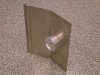
Nice piece.
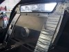
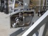
My engine uses the stock length water pump which is why when I moved the engine forward, the bulkhead also needed to be moved forward 3/4 inch and the cover re-done. I should have used the short nose Ford water pump, live and learn. One inch wide neoprene was additionally added all around the outside of the new metal flange inside the cockpit. The aluminum cover clamps tight against the hard molding on the flange and slightly compresses into the neoprene outside the flange. The neoprene conforms to the flat backside of the engine cover for a total water and vapor proof seal.
Both sides of the engine cover were layered with DynaMat and carpet glued to the cockpit side. Because the engine cover is flat, it can be lifted sideways out of the car to service the front of the engine without removing the seats. A f.ireproof metal engine cover is a very easy project and a really good idea for early CAVs.
Both sides of the engine cover were layered with DynaMat and carpet glued to the cockpit side. Because the engine cover is flat, it can be lifted sideways out of the car to service the front of the engine without removing the seats. A f.ireproof metal engine cover is a very easy project and a really good idea for early CAVs.
Last edited:
That was the salad and this is the meat.
I have always been a bit concerned by the way early CAVs have the ZF transmissions supported only by the cast metal ears on top of the ZF case. It is just too much like a big pendulum. Original cars have motor mounts, dog ears on top of the ZF, and two heavy duty motor mount like bushings on the bottom sides of the bell housing. I would like my motor and transmission to be anchored equally well.
Basically I though the easiest route would be to retain the stock CAV rear frame and just add a simple bracket to support some of the transmission weight and minimize the waggle at the end of the transmission during hard cornering. Of course the hard parts are designing a bracket around the right side of the ZF with the protruding shift mechanism box and strengthen the tubing under the transmission so it will support the load. I also wanted the new mount to be as unobtrusive as possible.
By keeping the ZF mounting ears and adding a mount at the rear it should allow for a normal amount of torque-twist movement but the transmission and motor will be kept exactly axial with the length of the car. I also want to reduce the load on the crossmember/ZF ears and shift most of the static load to a new transmission bracket.
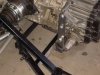
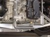
This picture shows the starting point with a single 1 inch square tube running under the rear end of the ZF trans.
I have always been a bit concerned by the way early CAVs have the ZF transmissions supported only by the cast metal ears on top of the ZF case. It is just too much like a big pendulum. Original cars have motor mounts, dog ears on top of the ZF, and two heavy duty motor mount like bushings on the bottom sides of the bell housing. I would like my motor and transmission to be anchored equally well.
Basically I though the easiest route would be to retain the stock CAV rear frame and just add a simple bracket to support some of the transmission weight and minimize the waggle at the end of the transmission during hard cornering. Of course the hard parts are designing a bracket around the right side of the ZF with the protruding shift mechanism box and strengthen the tubing under the transmission so it will support the load. I also wanted the new mount to be as unobtrusive as possible.
By keeping the ZF mounting ears and adding a mount at the rear it should allow for a normal amount of torque-twist movement but the transmission and motor will be kept exactly axial with the length of the car. I also want to reduce the load on the crossmember/ZF ears and shift most of the static load to a new transmission bracket.
This picture shows the starting point with a single 1 inch square tube running under the rear end of the ZF trans.
This is the picture for the prior paragraph.
Maybe the picture will upload this third try.....
Oviously I am having a little trouble posting pictures in the new forum. Another try here to show the stock CAV rear frame before it was modified to support the ZF tansmission.
And now back to the thr.ead which is alr.eady in progress…..
In this case, being a bit ob.sessive and compulsive had it up side. I built half a dozen mock-ups out of cardboard and carried them around with me on a week long business trip. Only one mock-up survived the trip and did not get crushed in my suitcase so I considered that equivalent to Darwinian selection and scientifically decided to use that design.
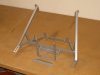
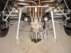
The final prototype design is shown here. A U-shaped bracket with a flat bottom bolts to the sides of the transmission case. The 1 inch square tube across the bottom of the stock CAV frame was reinforced with a vertical member that included a drop center horizontal shelf. The flat bottom of the U-bracket sits flat in the shelf. Strips of dense neoprene rubber are sandwiched between the shelf and the U-bracket and above the U-bracket with a length of metal angle on top to cap it off. The entire sandwich is then bolted together. This allows the movement of the transmission to be damped in all directions.
In this case, being a bit ob.sessive and compulsive had it up side. I built half a dozen mock-ups out of cardboard and carried them around with me on a week long business trip. Only one mock-up survived the trip and did not get crushed in my suitcase so I considered that equivalent to Darwinian selection and scientifically decided to use that design.
The final prototype design is shown here. A U-shaped bracket with a flat bottom bolts to the sides of the transmission case. The 1 inch square tube across the bottom of the stock CAV frame was reinforced with a vertical member that included a drop center horizontal shelf. The flat bottom of the U-bracket sits flat in the shelf. Strips of dense neoprene rubber are sandwiched between the shelf and the U-bracket and above the U-bracket with a length of metal angle on top to cap it off. The entire sandwich is then bolted together. This allows the movement of the transmission to be damped in all directions.
Attachments
Last edited:
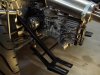
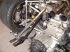
The square tube struts that angle down from the chassis also needed to be relocated and strengthened. The original struts DO clear the half shafts from the ZF but they only have 1/4 inch of clearance to spare on full bump and I would like more margin. In addition the struts needed to be relocated to directly support the new reinforced transmission crossmember. This picture shows how the original parts were left in place to keep everything aligned while the new struts were added.
Part of the criteria for the new struts was that they had to be located so that all the suspension bolts could still be independently removed without removing the rear frame or any other unnecessary parts. The upper parts of the struts have also been secured by 2 bolts on a 1/4 inch thick plate (similar to MDA) instead of by a single bolt.
Part of the criteria for the new struts was that they had to be located so that all the suspension bolts could still be independently removed without removing the rear frame or any other unnecessary parts. The upper parts of the struts have also been secured by 2 bolts on a 1/4 inch thick plate (similar to MDA) instead of by a single bolt.
Attachments
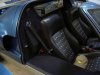
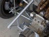
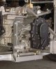
This is the finished rear frame with the ZF components all powder painted in viagra silver. The old struts and extra rear body hinge mounting pads have been removed. Additional upright tubes were also added for strength. Note that the lower struts angle up and are not horizontal. The entire package is deceptively rigid.
Attachments
Before the U-bracket could be bolted to the sides of the transmission, an access hole had to be cut into the backside of the shifter box. In this picture you can see where the access hole was added, the bottom bolt for the U-bracket installed, and then a plug inserted to re-seal the hole. For anyone curious, the hole was drilled in the case with the transmission and shift linkage installed in the car. A Forstner bit was used which shaved away layers of material like a lathe and produced a hole with clean square edges.
Attachments
Last edited:
The bottom neoprene pads were installed and shimmed up to lift the end of the ZF until the new bracket was supporting most of the weight and the ears of the ZF trans at the crossmember were almost unloaded when the car was at rest. McMaster-Carr has 1,001 shore rated densities of neoprene and with 12 square inches of area to work with, it should be easy to fine tune the ZF mount to any desired degree of control.
Attachments
Super-clean installation on a beautiful car. Well done, Bob.
bchildress said:This is the finished rear frame with the ZF components all powder painted in viagra silver........ The entire package is deceptively rigid.
Now there's a unique way to get a stiff chassis......
John
Last edited:
Finally, the top cap was added and bolted in place. The cap basically completes an enclosure around the neoprene so that it can only compress and cannot squirt out the sides. I suppose it also protects the neoprene from road chemicals, UV rays, and STDs. 3/8 inch diameter bolts and bolt holes were used in the bottom shelf and the top cap. 5/8 inch holes were used in the U-bracket to allow for mis-alignment and so that it could squirm around without any metal contact.
Attachments
From almost any viewpoint, the new ZF bracket is very discrete and not particularly noticeable. I am sure this design has been used before and it is probably on any number of different types of cars. Nothing like reinventing the wheel. Nevertheless it seems especially appropriate for the original style CAV rear frame. If you go back and look at the last few pictures in Part V, you can clearly see the differences between this new design and the original stock CAV frame
Attachments
Similar threads
- Replies
- 15
- Views
- 4K
- Replies
- 42
- Views
- 12K
- Replies
- 3
- Views
- 3K