Classic HorsePower Scratch GT40

Devin

Supporter
Hey Y’all (West Texas lingo for “everyone”)

Long time lurker/dreamer/collector of various parts here. I’m finally at that stage in life where I had to commit to getting started on this adventure or move on to other life goals & priorities.

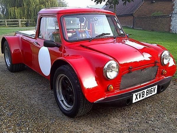
My experience over the last 35+ years has been primarily with Mustangs, Porsches, BMWs, and Cobras amoung various other muscle cars and trucks from the 1940s to the 80s. The GT-40 was my “unicorn” and have begun the build to make it a reality.

After weighing budget, time and my experience, I have chosen to truly make this 40 a custom build to fit me as a taller (6’1”) individual yet make it as true to the original look (to the untrained eye) for the major key features of the car.

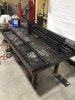
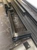
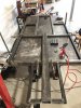
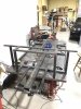
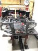
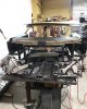
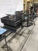
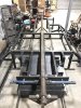
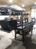
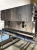
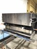
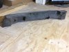
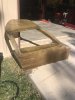
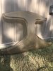
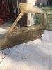
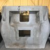
After acquiring the major body shells (some almost 20yrs ago), front, rear clamshells, roof/spider skins, door skins, sill covers, and dash. After committing to a custom build vs buying a manufactured kit, I’m sourcing things as I go along and face dimensional & fabrication challenges but that is the “fun” of a custom build to me,

Devin
Abilene, TX
 

Attachments

  • C34407FC-9248-47A1-A42F-3FA9C5604D01.jpeg
    C34407FC-9248-47A1-A42F-3FA9C5604D01.jpeg
    362.3 KB · Views: 482
  • 59F481DA-F17F-4B91-B7CC-CD8799FE06DD.jpeg
    59F481DA-F17F-4B91-B7CC-CD8799FE06DD.jpeg
    297.4 KB · Views: 476
  • 31F258AE-0507-423A-B8A4-407BBEA05797.jpeg
    31F258AE-0507-423A-B8A4-407BBEA05797.jpeg
    256.5 KB · Views: 452
  • 5D5DE66E-90FC-4AE9-8660-071F28CC487F.jpeg
    5D5DE66E-90FC-4AE9-8660-071F28CC487F.jpeg
    274.2 KB · Views: 429
  • F1AD470F-9D6E-4945-9945-2ABDD1DD7E58.jpeg
    F1AD470F-9D6E-4945-9945-2ABDD1DD7E58.jpeg
    222.9 KB · Views: 453

Devin

Supporter
For my chassis, I’ve committed to the ActivePower/ Corvette C-5 suspension design for ease of domestic US parts and maintenance. With that being said, I’ve varied from the standard AP chassis in several ways for added interior room and to meld the various previously sourced body parts.

The following is a summary of what I’m envisioning the final specs:

- 2” longer wheelbase with added 2” between interior leg space & engine bay room
- SBF (289-347ci) carbureted with Porsche Boxster S (6 sped)
- 15” BRM or Halibrand replica wheels (or 17 if not practical)
- LHD with center shift (Boxster cable system)
- Traditional black low tech interior with AC (Texas heat!)

With all that being said, I am new to TIG welding but have years of MIG welding, ASE certificates in brakes & suspension, and have access to an Aero/Mech Engineer for sanity check on design & materials.

I started with chassis welding in October and here are the first stages of my build.
 

Attachments

  • D8C8F913-1609-41C7-A937-F5787F4AB13C.jpeg
    D8C8F913-1609-41C7-A937-F5787F4AB13C.jpeg
    264.7 KB · Views: 438
  • 7595AF3D-33D5-4C41-BA20-C3C03278CB40.jpeg
    7595AF3D-33D5-4C41-BA20-C3C03278CB40.jpeg
    248.9 KB · Views: 430
  • 44894268-5975-4159-A86F-237517F3D8C6.jpeg
    44894268-5975-4159-A86F-237517F3D8C6.jpeg
    269.1 KB · Views: 425
  • 33D8640F-24A1-46FC-9FAF-6352849A6E5E.jpeg
    33D8640F-24A1-46FC-9FAF-6352849A6E5E.jpeg
    238.2 KB · Views: 396
  • B2070113-7C86-447A-9093-075218B61F0B.jpeg
    B2070113-7C86-447A-9093-075218B61F0B.jpeg
    248.6 KB · Views: 371
  • 45DCBBC7-D3D4-4000-A0F8-4BA696B64483.jpeg
    45DCBBC7-D3D4-4000-A0F8-4BA696B64483.jpeg
    204.1 KB · Views: 371
  • 750F9FD9-1794-42DA-A184-837EBE2C36F8.jpeg
    750F9FD9-1794-42DA-A184-837EBE2C36F8.jpeg
    235 KB · Views: 413

Devin

Supporter
More TIG welding and fab for the suspensions pieces...had a local metal shop CNC cut the mounting brackets & sheet metal plates according to plans. Of course they never just fit the first time even though everything is “within spec” of dimensions so a few more hours of thought and work are always the rule for custom building.
 

Attachments

  • FEA742E2-93C7-4A7F-A8B1-820E63F06EE8.jpeg
    FEA742E2-93C7-4A7F-A8B1-820E63F06EE8.jpeg
    274.3 KB · Views: 424
  • D2FB3412-6C5C-454D-80D6-BCBE43E70BAC.jpeg
    D2FB3412-6C5C-454D-80D6-BCBE43E70BAC.jpeg
    235.8 KB · Views: 410
  • 338F0037-FB70-49F3-B7EB-E3954429136B.jpeg
    338F0037-FB70-49F3-B7EB-E3954429136B.jpeg
    166.5 KB · Views: 396
  • D1C779B9-DC82-451B-B0CC-3050605305AD.jpeg
    D1C779B9-DC82-451B-B0CC-3050605305AD.jpeg
    265.3 KB · Views: 389
  • BF1ACF4E-E647-4A04-A01B-7FFA726D2A62.jpeg
    BF1ACF4E-E647-4A04-A01B-7FFA726D2A62.jpeg
    264.9 KB · Views: 399
  • 3D7722EE-8DFF-4A38-8A3A-229586680F0F.jpeg
    3D7722EE-8DFF-4A38-8A3A-229586680F0F.jpeg
    257.6 KB · Views: 389
  • AF3E7F2A-54A2-455B-AC59-66737B4C2BE7.jpeg
    AF3E7F2A-54A2-455B-AC59-66737B4C2BE7.jpeg
    222 KB · Views: 394
  • C2F79F97-3412-4D68-BC64-0889F51D1FBA.jpeg
    C2F79F97-3412-4D68-BC64-0889F51D1FBA.jpeg
    216.7 KB · Views: 400
  • 701936A7-1592-4486-8E94-5510AD2F6EC5.jpeg
    701936A7-1592-4486-8E94-5510AD2F6EC5.jpeg
    271.9 KB · Views: 431

Devin

Supporter
Mostly finished up initial welding (need some more seams done on rotisserie) of the main chassis and suspension mounts. Need upper mounts of the rear shocks but will wait until I have those in hand to get the angle correct.

Also reworked the drivers fuel pod to enable the installation of Tornado fuel tanks...need to do the same to the passenger side (right) next. Relearned a valuable lesson to have the parts in hand before final welding. As we all know, no two replica manufactures dimensions are the same...my first attempt at the fuel pod was about 1/4” too narrow but more critical was that the height of the tank was 3/4” taller than my planned space which would be the lowest point of the car...not acceptable. Cut and replaced the side bar of the pod from 1.5” square to 3/4” square. Yes, less strength (not completely necessary in that area) and side impact protection however I added 3 additional cross braces for added strength. More diagonal bracing will be added in multiple areas once on the rotisserie as well.
 

Attachments

  • 0AF69B2A-B546-4DD6-9E52-01986F0DFC95.jpeg
    0AF69B2A-B546-4DD6-9E52-01986F0DFC95.jpeg
    207.3 KB · Views: 351
  • BC5505E4-E06C-4923-91E9-62B2EA2DB765.jpeg
    BC5505E4-E06C-4923-91E9-62B2EA2DB765.jpeg
    246.1 KB · Views: 338
  • FFFD8299-EF22-4919-9232-66F6B455045D.jpeg
    FFFD8299-EF22-4919-9232-66F6B455045D.jpeg
    277.5 KB · Views: 397

Devin

Supporter
Finally got the chassis off of the welding table for the first time and mounted to a rotisserie.

Funny thing is that I inherited this homemade rotisserie with a past Austin Mini restoration and stored it away for several years. Thought it might work so I brought it out to measure and see if I could modify it...all I needed was to relocate the mounts and figure out how to attach to the chassis!

Once mounted, it’s top heavy (of course) so will have to work out a counterweight to assist in rotating it but for now welding on the underside is a luxury.
 

Attachments

  • 94AF6CDE-0950-47DE-9321-587BCE075730.jpeg
    94AF6CDE-0950-47DE-9321-587BCE075730.jpeg
    367.4 KB · Views: 365
  • 66801E1D-1460-4027-A71F-AFAFC5611A3E.jpeg
    66801E1D-1460-4027-A71F-AFAFC5611A3E.jpeg
    238.6 KB · Views: 370
  • B3444ED8-4B8C-41EB-9214-FEF05DAA2DC1.jpeg
    B3444ED8-4B8C-41EB-9214-FEF05DAA2DC1.jpeg
    287.8 KB · Views: 336
  • 5A563F7D-3D55-468C-BC8D-1F710043F503.jpeg
    5A563F7D-3D55-468C-BC8D-1F710043F503.jpeg
    233.7 KB · Views: 355

Devin

Supporter
Been a busy couple weeks here at Classic Horsepower garage.

Had to make emergency trip back to KS but decided it was the right time to help my dad’s forever best friend dig out his 65 Galaxie 500XL (390FE) after its 40+yr hibernation in a barn. Needless to say I’m reviving it back to life so will take some time away from the GT40 build but am determined to keep making small progress weekly.

Here’s the 68-72 Sprite/Midget steering rack I just got and it’s mounting on my scratch chassis. Sorry forgot who here suggested the muffler/pipe clamps but looks like they will work like a champ with raising them from the mounting surface with a 1/8” plate spacer!

Figured out the old BMW wheels from my son-in-laws car will work the same as the Corvette lug pattern and will serve temp duty until body is somewhat mounted for a custom rim order. So think getting it on its feet might be next after welding the rear upper coilover mount.
 

Attachments

  • 59AD3C8D-7748-4E3C-8351-60C7F9BDE70D.jpeg
    59AD3C8D-7748-4E3C-8351-60C7F9BDE70D.jpeg
    234.9 KB · Views: 305
  • 3609A649-5042-4545-8994-B46FB2C1E2E3.jpeg
    3609A649-5042-4545-8994-B46FB2C1E2E3.jpeg
    205 KB · Views: 297
Have you looked at suspension geometry with regards to bump steer? You may want to temporarily mount that rack with tack welds, get the a-arms mounted, and see if the bump steer would benefit from moving the rack up or down, although up looks tight there. That being, if it's just a street cruiser, I wouldn't get too worked up about bump steer.
 

Devin

Supporter
Have you looked at suspension geometry with regards to bump steer? You may want to temporarily mount that rack with tack welds, get the a-arms mounted, and see if the bump steer would benefit from moving the rack up or down, although up looks tight there. That being, if it's just a street cruiser, I wouldn't get too worked up about bump steer.
I’ve been referring to other AP build pics here and going with how is appears how theirs have been mount (mostly to the top of the cavity). Yes I have tack welded it just in case there need to be readjustment for bump steer but also plan on using variable spacing with the end links since the corvette tie rods are metric and the steering rack is SAE 5/8”-18 threaded.
 
The tie rods are a moot point. The corvette upright steering arm have the big end of the taper on the bottom intending the tie rod to be below the arm. With this rack location, you have to use an adapter and a heim above the arm. Since you're already forced to ditch the oem tie rod, you can correct bumpsteer with the spacer between the upright and the heim.
 

Devin

Supporter
The tie rods are a moot point. The corvette upright steering arm have the big end of the taper on the bottom intending the tie rod to be below the arm. With this rack location, you have to use an adapter and a heim above the arm. Since you're already forced to ditch the oem tie rod, you can correct bumpsteer with the spacer between the upright and the heim.
Brian, do you have a pic and/or part# of what folks are using for the heim “adaptor”?
 
It's something Chris provided. It's just a bolt and a cone shaped spacer. I have a more solid idea for my permanent solution, stay tuned and I'll share.

It'll be a tapered sleeve with a slit that fills the void you would have if you just stuck a bolt with a washer in the hole. I'll slit it on one side so as the bolt is tightened, the cone is pulled in to the taper of the arm chucking the bolt like a collet. Then a machined to size conical spacer to brace the bolt against the bending forces of steering.

I'll try to get you a pic of what was supplied in the next few days. Where you are now, a cheese grade bolt and piece of tubing will suffice for mock ups.
 

Devin

Supporter
It’s been a while since my last update...

Got “distracted” from the ‘40 project with a life long family friend’s 1965 Ford Galaxie 500XL Hardtop. It was parked in a barn back in the 1970’s with 54k miles due to a smoking #7 cylinder. Needless to say, I had to pull the engine and do a complete rebuild on the 390FE. Boy did I learn a lot of FE particular lessons & technical specifics along the way...may be useful for a future FE powered GT40??

Well back to this project.

I finally bought a media blasting cabinet and reconditioned my C5/6 suspension pieces by glass beading and then light sanding to get back some shine to the aluminum. Also installed new ball joints, wheel bearings and Prothane bushings. It was a lot of work but well worth doing it right now and having it all ready once the chassis is complete and powder coated...besides, one of the wheel bearings was almost frozen so needed it easy to roll to move it around the shop.

Was also able to mount the rear suspension and coilover stocks to tack the upper mounts into place in prep for getting it on all four wheels in the near future for the next phase of the project...body mounting. Once on the ground, I’ll be giving it a good four wheel alignment on my Hunter machine to make sure I’m working with a good base for the wheel openings and mounting locations. Also need to finish up the steering rack & rod end solution to the front uprights.
25E57EAA-96B0-466C-B6B9-59D124A39040.jpeg
38E9D9DF-740B-4683-B46F-FE29AD934F52.jpeg
1ACE636B-EF5E-46C9-A983-8A03C781A7FE.jpeg
 
Last edited:

Devin

Supporter
Got it off the rotisserie and on its four feet this weekend. Next is getting the chassis on the alignment machine to get things square and placed for a good reference during body shell mounting, followed by steering shaft mounting
A5F14235-5B2B-4561-8A12-3ED7D1ED6EC3.jpeg
1A1E229C-A26F-441D-B263-25630BD38C4B.jpeg
A66E8AC4-3353-4515-BF98-EE91371D8DA4.jpeg
CD1C031D-94FD-4677-97B3-9EDBA42A9C2E.jpeg
21F8844F-C044-436B-A614-2B9DDEC16333.jpeg
C0CA79D4-E428-43B6-B0AD-0DBF8EA752DF.jpeg
 

Devin

Supporter
More progress on scratch build 40.

Was able to get it on the alignment rack and dial it in at set ride height (with wooden shocks) with good results and a bit more adjustable if negative camber is needed later.

After achieving a square foundation, I mocked up everything to locate the FFR GTM windshield and rear bulkhead. With the supposed original spider splash molds...I had to section and re-curve the windshield base to match the one I have. After that I was able to bond the bottom support piece to the sectioned top piece with 3M panel bond adhesive and prep for fiberglass & epoxy work.

The rear bulkhead upper support bar which I thought could be straight (using 1.5” square tubing) ended up being a bit too low for the window opening so had to section into more of an arc for better curvature to match the roof line.

Next will be fabrication of the rear legs of the bulkhead roll bar.
678B3941-BBBE-4CB7-B022-EDA3C31915A0.jpeg
A75A35AE-D740-4445-98F7-55A5397DC6C5.jpeg
444EFF03-42C6-42CE-9DBF-A6B314325DE4.jpeg
29B83D9C-A7DD-4AD0-BFC8-3837F287D081.jpeg
75EC4676-638C-4C52-8F05-7B7F8F8852C4.jpeg
3677C0C9-9420-4673-830C-3BDDA94B9A2F.jpeg
79666127-1E45-498E-AE3D-E3876CE1A72A.jpeg
 

Devin

Supporter
Bulkhead window & engine access panel framed.

Question to those with completed cars…how often do you all need to remove and get access to the front of the engine via the cockpit? I have both drive on 4 post and 2 post lifts so thinking once the car is completed I should only need to do that when/if a water pump or maybe alternator/fan belt needs servicing??

View attachment 130382
E6BA071F-787D-477B-A491-AB64DB5E465A.jpeg
 
Back
Top