DC&O Vacuum

I know Ross has one, curious to know what anybody has their DC&O set at. I have all the cylinders set at 4 pounds (using a synchrometer) except that 3 and 5 are at 10. For some reason they seem to act like 'master' seetings with the others acting as slaves. I'm getting a bit of backfire on deceleration, I think from 3 & 5. When I've tried to drop the numbers lower the engine wants to die. I'm going to try and raise up the others a bit then drop 3 & 5 and then drop the rest to try and bring it in more slowly. I'd be real curious to know any secrets that anyone might be willing to share.

Many thanks.
 
Pat ,I also have a DC&O manifold that has the throttle bodys linked in pairs,I`m about to start up so am interested in what you turn up with this post.
Advice to date indicates problems on deceleration and low revs with backfire
____________________

burnsy RF104
 

Ross Nicol

GT40s Supporter
Hi Pat and Burns
I don't know if you guys saw a recent post of mine where I mentioned having improvements made to my DC&O throttle bodies. I had quite bad stiction when first applying the throttle after being off it and this caused quite a bang when the butterflies finally opened. It turns out that there are a few problems with the manifolds as they come from DC&O and RF were buying raw manifolds and having throttlebodies fitted of a much higher standard by a Ford engine guru here in Melbourne. He explained the problems to me
1/ Throttle body machining not accurate
2/ Shafts (which float in the bearings) allow jamming of the butterfly edge.
3/ Shafts not straight and coupler between pairs not helping trueness.
4/ grub screws on shaft couplers not allowing accurate adjustment

All these things are sorted on mine now and I have sprung loaded screws that adjust each individual trumpet accurately. A couple of things I learned along the way, you should adjust the trumpets with the throttle totally relaxed and also as the throttle bodies begin to open.Also I found it necessary to use green loctite on the adjusting screws to lock them after adjustment. I'll take a photo of the new layout if you would like to see it.

Ross
 

Peter Delaney

GT40s Supporter
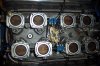
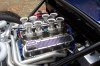
I have the stock DC&O setup - 4 pairs of TB's, each on a common shaft. It was a real bitch to set up, but it can be done. Lots of loosening/tightening the hold-down nuts to get perfectly free shaft action on each pair, then gang them up on each side, repeat above, etc, etc.

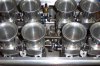
Once we got it all working freely, final synchronisation of all butterflies was a bit primitive, but it worked. A vacuum gauge in the top of each trumpet got each pair fairly close to the other pairs, then the final adjustments were done by gently tapping the butterflies with a screwdriver !

With Steve Cox (THE Autronic Guru) at the helm, we got the only 8-stack SB ever to pass the old ADR 79/01 emissions tests (about 2 years ago).

It all now works fine - no lags, no spits, no backfires ! All it took was time & money ! If I was doing it again, I would use the same individually adjustable RF setup that Ross mentioned.

BTW - watch the circlips that hold the bearings in on the shafts - my shafts had no grooves for the circlips to lock into, so over time, some of them moved along the shafts & allowed the bearings to pop out ! I solved that one by putting short lengths of slit fuel hose between the circlips on each body-pair, & collets on the free ends of the shafts - cheap, simple, & it works !

The other issue to watch on a DC&O manifold is where you take off the various vacuum hoses. We had all sorts of trouble when we took everything off the one manifold point, but when we separated things - 1 purely dedicated for the ECU MAP feed & the other for power brakes, etc.. all was fine.

Kind Regards,

Peter D.
 
Thanks guys, I thought it might come down to lots of little adjusting. I would love to see a picture to compare what I have stock from RF (spring 02) to what you are running now.
 

Peter Delaney

GT40s Supporter
This pic shows the linkage setup (with the fuel hoses & collets to keep the shaft bearings in place).

The other big change that I made from the DC&O standard is to have the fuel rails & injectors inside the TB's (better fuel/air mix & may explain why it got thru the emissions tests).
 

Attachments

  • DCP_0593 (Medium).JPG
    DCP_0593 (Medium).JPG
    97.9 KB · Views: 737

Peter Delaney

GT40s Supporter
This early one shows the fuel rails installed inside the TB's - but note the shaft bearing heading south on the rear RHS shaft (hence the collets, etc) !
 

Attachments

  • Fuel-3 (Medium).jpg
    Fuel-3 (Medium).jpg
    81.7 KB · Views: 697

Peter Delaney

GT40s Supporter
This is what I understand to be the standard DC&O / RF setup - fuel rails outside & individual adjusters between each pair of TB's :
 

Attachments

  • EFI HM2 (Medium).jpg
    EFI HM2 (Medium).jpg
    72.1 KB · Views: 695

Ross Nicol

GT40s Supporter
Hi Peter
That last pic is what I have now and as Pat got his manifold from RF it should be what he has too.The old setup of mine had plastic couplers and grub screws between trumpets a nightmare to adjust which is why I didn't.
I still have the odd cold misfire but all in all it idles nicely and is much more driver friendly.
Ross
 

Peter Delaney

GT40s Supporter
Hi Ross,

Anything plastic must have been real fun to deal with in the engine area - even the fake black plastic bolts in the top of the Edelbrock rocker covers melted on mine !!

Pat should be good to go with the individual adjusters - all that is needed is patience !

How have you found the spring-loaded setup in terms of staying put over time (any Locktite required, etc) ?

Kind Regards,

Peter D.
 

Bill Hara

Old Hand
GT40s Supporter
Peter and Ross

I believe DC&O have changed the design of their manifold now so that there is only 1 adjuster per bank, ie 2 adjusting screws for butterfly position in total.
 
Peter, thanks forthe pictures! As Ross says, the last picture you posted is exactly what mine looks like today. I'm going to have a chance over the coming weekend to dive back into it and see what I can do. Your idea of spinning the horns around to feed from the inside would also improve the spacing between the rear clip and the fuel rail. Lots to think about!
 

Peter Delaney

GT40s Supporter
No problem Pat - let me know if you need any other pics, etc.

The biggest problems in running the fuel rails on the inside were :

- The original rails could not be used - simply too bulky - hence the skinny ones that I had to get fabricated from steel tube, pre-made injector housings, AN fittings, etc - all tig welded.

- Things are so tight up the middle that it is quite a challenge to connect/disconnect the injector connectors, and to get to the centre linkage components.

All in all, I doubt that it makes a noticable difference to performance - it may be a bit of a help with emissions, & IMHO it does make for quite a "clean" look around the top of the engine.

A lot of work, but probably not worth the effort !

The real secret to getting the old DC&O paired setup to work is to spend a lot of time fiddling with the tensioning down of the TB's so that you avoid the butterfly binding problem that Ross mentioned. Not easy, but it can be done.

Kind Regards,

Peter D.
 
Back
Top