

You are using an out of date browser. It may not display this or other websites correctly.
You should upgrade or use an alternative browser.
You should upgrade or use an alternative browser.
Expansion tank plumbing help
- Thread starter Buttinz
- Start date
In need of some insight on expansion tank plumbing please. I brought up in my build thread thought i had it but then found some posts that is completely different routing. I was going to eliminate bypass hose and go from bottom of expansion tank to upper barb on WP then top expansion tank to water neck creating the bypass and heater core to lower barb on WP and radiator then 1/8 npt on expansion to overflow tank.I found a detailed write up by another member that seams like many are off that info. The bypass hose was left alone and went from bottom of expansion tank to lower WP barb,top expansion tank to top of radiator and 1/8 npt on expansion tank to overflow Heater core was spliced onto the 2 radiator tubes up front?
Thank you
Thank you
My situation,
No bypass as I am running an empty waterpump as there's an electric Davies Craig waterpump doing its job far better.
With the mechanical pump I was running the bypass.
Upper waterpump to expansion tank.
Small bleed line from upper water hose (which is the most highest point of my cooling system) to expansion tank.
Small bleed line from top radiator to expansion tank.
From the top of my expansion tank I have a small hose to the coolant reservoir.
Photo: bottom of the reservoir comes from the waterpump, left two small tubes are bleed lines from top radiator and top upper radiator hose ( you can see it sitting in front of the airfilter next to the T bolt)

On top of the waterpump you'll see the hose that goes expansion route. (when I was running the mechanical pump)

radiator bleed line from top radiator (see small rubber hose into copper line)

My coolant reservoir on the other side. Cap is an empty cap so it can breathe.

In my current setup my waterpump is empty, but coolant system still the same with the exception of the bypass which is no longer needed with an electric pump & controller.


No bypass as I am running an empty waterpump as there's an electric Davies Craig waterpump doing its job far better.
With the mechanical pump I was running the bypass.
Upper waterpump to expansion tank.
Small bleed line from upper water hose (which is the most highest point of my cooling system) to expansion tank.
Small bleed line from top radiator to expansion tank.
From the top of my expansion tank I have a small hose to the coolant reservoir.
Photo: bottom of the reservoir comes from the waterpump, left two small tubes are bleed lines from top radiator and top upper radiator hose ( you can see it sitting in front of the airfilter next to the T bolt)
On top of the waterpump you'll see the hose that goes expansion route. (when I was running the mechanical pump)
radiator bleed line from top radiator (see small rubber hose into copper line)
My coolant reservoir on the other side. Cap is an empty cap so it can breathe.
In my current setup my waterpump is empty, but coolant system still the same with the exception of the bypass which is no longer needed with an electric pump & controller.
I think this is how my orig setup would be before i found other post. I will post pics when i get home but of exact setup but Below is pics of my components to make easier.I was going from bottom of expansion to upper barb on pump, barb on water neck to top mid of expansion thank, top of expansion tank to overflow. 1 side of heater core to lower WP barb. Does that seam right? Or an i overthinking lolMy situation,
No bypass as I am running an empty waterpump as there's an electric Davies Craig waterpump doing its job far better.
With the mechanical pump I was running the bypass.
Upper waterpump to expansion tank.
Small bleed line from upper water hose (which is the most highest point of my cooling system) to expansion tank.
Small bleed line from top radiator to expansion tank.
From the top of my expansion tank I have a small hose to the coolant reservoir.
Photo: bottom of the reservoir comes from the waterpump, left two small tubes are bleed lines from top radiator and top upper radiator hose ( you can see it sitting in front of the airfilter next to the T bolt)
View attachment 127135
On top of the waterpump you'll see the hose that goes expansion route. (when I was running the mechanical pump)
View attachment 127136
radiator bleed line from top radiator (see small rubber hose into copper line)
View attachment 127138
My coolant reservoir on the other side. Cap is an empty cap so it can breathe.
View attachment 127140
In my current setup my waterpump is empty, but coolant system still the same with the exception of the bypass which is no longer needed with an electric pump & controller.
View attachment 127137
View attachment 127139
I've seen a lot of complicated systems. One thing you need to make sure, coolant added to the tank can make it to the water pump intake, and bubbles from the system can make it to the tank, and be replaced with coolant.
Your tank needs to be mounted higher than the water pump and the tube from the tank to the pump not have a hump that will "lock" water from gravity feeding to the pump.
Ideally, I would say the heater return should go into the tank too. The heater feed should be from one of the ports on top of the manifold as it's the highest point where air can accumulate. The goal is all air get trapped and funneled to the tank.
Did you say you were tapping the radiator hoses for the heater? One note, that means the heater will not do anything until the engine is up to temp enough to open the thermostat and full flow the radiator.
YMMV
All 3 hose connections to the waterpump are on the "suck" side. So the other heater hose needs to be hot supply water. It needs to come off the intake if possible.
You need the bypass hose, but you can get away without it if you drill a hole in the thermostat. The bypass circulates water in the block even if the thermostat is closed.
Vintage Air makes a H pipe for heaters, especially in small block chevy applications. You could hook the heater to the thermostat housing and water pump with the H pipe so when the heater valve is closed, it bypasses, and the heater return to the tank and then to the WP nipple.
Seems to check the boxes.
Side note, small block chevys, unlike mopar and fords, do not have a bypass hose. So if the heater circuit is bypassed, the engine will overheat from a cold start as there is no water flow from the head to the thermostat. The cold water in the intake will keeps the thermostat closed, and the hot water in the block and heads as the engine melts down. A down and dirty fix is a bleed hole in the t-stat so some water from the head is always flowing to the T-stat. Chevy heater valves don't just shut the water flow through the heater core. They also bypass water so hot water will enter the intake manifold.
I guess it gets complicated because every car has different special things.
On my Kelmark, I made a big reservoir for a tank, and the return water from the radiator fed it, and it fed the water pump. I was thinking something like that for my car, but we'll see after I get all of the turbo and intercooler plumbed in. Cooling will work around what is dictated by intake plumbing.
pics below are my car. So if im thinking right lol the bypass hose stays, bottom expansion tank to lower WP barb, middle expansion to top of radiator,top expandion to overflow and where i pit my temp sensor is what needs to go to heater core then heater core to radiator? I know, i just smh myself lol


Bill Kearley
Supporter
Use caution Joe. A SMALL hole in the thermostat is good fore bleeding air out of the system while filling. Depending on the size of the hole will dictate warm up time. Don't make a big one, 1/8 is good enough. You need a bypass hose.
Howard Jones
Supporter
Run a hose from the 90-degree bung that was used for the heater system before you gutted your pump to the bottom of the expansion tank. The reason for this location is that this is the coolest water in the system and is right at the inlet to the engine. My gt40 expansion tank inlet hose is about a 1/2 ID and my SLC is an AN 10 so about 1/2 inch ID should do. You don't need a thermostat and therefore no need for a bypass with the DCEWP so this setup will work fine.
After 4 cups of coffee and an hour later in garage staring at car last night i think i have a plan lol.going from bottom of exp tank to lower barb on WP -12an,middle of exp tank to cool side of rad -6an. Going to remove my temp sender off manifold behind waterneck and put a 1/2npt to10an 90 swivel fitting to -10an T fitting with 1/8npt Port and ad a Y to that for temp sender and -3an bleed line to top exp tank than continue line to heater core in,then out of heater back into front cooling tube to rad on hot side. This should also become self bleeding system this way. Opinions on this?
Thanks
Joe
Thanks
Joe
Howard Jones
Supporter
An12 for the expansion feed is fine. Your choice of location for that is also fine. The air bleed lines work best at an-4, I ran one from the top of the radiator, as well as one from the top front of the intake, and added two from the rear of the intake to bleed the rear of the heads. The rear of the heads will be an important addition. You can tie them into the front of the intake and onto the expansion tank or go directly to the expansion tank. Here are a couple of pictures.
Attachments
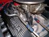
The borla stack injection dont have any on rear. Only 2 in front.An12 for the expansion feed is fine. Your choice of location for that is also fine. The air bleed lines work best at an-4, I ran one from the top of the radiator, as well as one from the top front of the intake, and added two from the rear of the intake to bleed the rear of the heads. The rear of the heads will be an important addition. You can tie them into the front of the intake and onto the expansion tank or go directly to the expansion tank. Here are a couple of pictures.
Howard Jones
Supporter
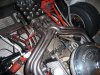
Tell us more about your engine especially the heads and the intake. One big straight down over view of the engine would help.
it’s a Shelby all aluminum 427w with AFR220cc heads,borla stack injectionTell us more about your engine especially the heads and the intake. One big straight down over view of the engine would help.
Howard Jones
Supporter
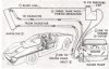
Ok, I have a much better picture, So first you can take the little piece of tubing with the plug in it that is intended to mount the coolant temp sensor out from the front near the pump and move it to either the same piece of tubing installed between the 90-degree silicone bend coming from the thermostat housing and the corrugated hose that I believe comes from the radiator via the sidepod tubing. This will free up a spot for other coolant system fittings.
Now you are sending coolant temp at the hottest point in the system, check!
Next, run the expansion tank coolant input from the water pump bottom heater port (the one that is plugged in your engine picture) to the bottom of the expansion tank. You will need to plug the top one that is used for the bypass hose since you will not be using it without a thermostat. Plug the other end also that goes into the thermostat housing. You don't need this anymore either. No heater correct?
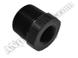
Now all that is left is the bleed system. For now, I think you might not want to molest your nice new engine so we will forgo the rear of the intake/heads ports. To add them will require you to remove the intake and drill and tap holes in the intake where the rear water passages are in the heads. The front bleed is required however, so you can use the port on the top of the intake that you now have the EW sensor in for that. Run that AN-4 line to the top side of the expansion tank. There you will need a "T" adapter so you can also run the bleed line from the radiator to the same spot. It looks like a AN-6 or 8 in the side of the tank. You can put a reducer in there and then use a 1/8 NPT pipe to AN-4 T. I think that this would come out nice and neat,
 www.anplumbing.com
 www.anplumbing.com
Now another question. Where are you sensing coolant temp for the water temp gauge?
Now you are sending coolant temp at the hottest point in the system, check!
Next, run the expansion tank coolant input from the water pump bottom heater port (the one that is plugged in your engine picture) to the bottom of the expansion tank. You will need to plug the top one that is used for the bypass hose since you will not be using it without a thermostat. Plug the other end also that goes into the thermostat housing. You don't need this anymore either. No heater correct?
Now all that is left is the bleed system. For now, I think you might not want to molest your nice new engine so we will forgo the rear of the intake/heads ports. To add them will require you to remove the intake and drill and tap holes in the intake where the rear water passages are in the heads. The front bleed is required however, so you can use the port on the top of the intake that you now have the EW sensor in for that. Run that AN-4 line to the top side of the expansion tank. There you will need a "T" adapter so you can also run the bleed line from the radiator to the same spot. It looks like a AN-6 or 8 in the side of the tank. You can put a reducer in there and then use a 1/8 NPT pipe to AN-4 T. I think that this would come out nice and neat,
NPT Male to NPT Female Reducer Bushing - Black - Aluminum
NPT Male to NPT Female Reducer Bushing - Black - Aluminum
www.anplumbing.com
A.N. Male Tee with NPT Male on Run - Black - Aluminum
A.N. Male Tee with NPT Male on Run - Black - Aluminum
www.anplumbing.com
Now another question. Where are you sensing coolant temp for the water temp gauge?
Appreciate your help/info thank you. I am running heat/AC.right now my temp sensor for gauge is behind T-housing. My temp sensor for computer is on other side of motor.what i came up with othernight is, remove temp sensor from behind T-housing and put a 1/2npt10an 90 with adapter to put sensor in that along with -3bleed hose back to top E-tank. Then 10an hose from that 90 coming out of intake to #1 port on heatercore.#2 port on heatercore continue to radiator (orange port) 6an hose from top cool side radiator back to middle port on E-tank.12an hose from Bottom port of E-tank to lower barb of WP.what you think?Ok, I have a much better picture, So first you can take the little piece of tubing with the plug in it that is intended to mount the coolant temp sensor out from the front near the pump and move it to either the same piece of tubing installed between the 90-degree silicone bend coming from the thermostat housing and the corrugated hose that I believe comes from the radiator via the sidepod tubing. This will free up a spot for other coolant system fittings.
Now you are sending coolant temp at the hottest point in the system, check!
Next, run the expansion tank coolant input from the water pump bottom heater port (the one that is plugged in your engine picture) to the bottom of the expansion tank. You will need to plug the top one that is used for the bypass hose since you will not be using it without a thermostat. Plug the other end also that goes into the thermostat housing. You don't need this anymore either. No heater correct?
Now all that is left is the bleed system. For now, I think you might not want to molest your nice new engine so we will forgo the rear of the intake/heads ports. To add them will require you to remove the intake and drill and tap holes in the intake where the rear water passages are in the heads. The front bleed is required however, so you can use the port on the top of the intake that you now have the EW sensor in for that. Run that AN-4 line to the top side of the expansion tank. There you will need a "T" adapter so you can also run the bleed line from the radiator to the same spot. It looks like a AN-6 or 8 in the side of the tank. You can put a reducer in there and then use a 1/8 NPT pipe to AN-4 T. I think that this would come out nice and neat,
NPT Male to NPT Female Reducer Bushing - Black - Aluminum
NPT Male to NPT Female Reducer Bushing - Black - AluminumA.N. Male Tee with NPT Male on Run - Black - Aluminum
A.N. Male Tee with NPT Male on Run - Black - Aluminum
Now another question. Where are you sensing coolant temp for the water temp gauge?
Thanks
Joe
Similar threads
- Replies
- 15
- Views
- 1K
- Replies
- 74
- Views
- 5K
- Replies
- 17
- Views
- 2K
- Replies
- 19
- Views
- 2K