

You are using an out of date browser. It may not display this or other websites correctly.
You should upgrade or use an alternative browser.
You should upgrade or use an alternative browser.
Pairing headers?
- Thread starter Peruch
- Start date
Pairing headers for try-y configuration ? (13726548 firing order)
Thanks
(1---2)---(3---4),,,,(5---7)---(6---8)
Jac Mac
(1---2)---(3---4),,,,(5---7)---(6---8)
Jac Mac
Many thanks and for 289 firing order ? (154263768)
Regards,
Many thanks and for 289 firing order ? (154263768)
Regards,
Stays the Same.
Jac Mac
Never knew that Ford built a 289 9 cylinder 
Honestly i´m new on V8´s and therefore would be very interrested in some details.
I´ve heard that some orignal GT 40 have used flatplane cranks.
Is this correct ?
Does anyone know if this cars sound is generated by the 180°crossover exhaust system or by a flat plane crank ( what i think is) ( or both)
YouTube - Gt40 losses control
( just love this sound !btw is this an original ?)
Has anyone in this forum built an engine with an flatplane crank ? What where or are the experiences with it ? Off course it will rev better, but how about the vibrations ? are there flatplan cranks available in the market for a 302 or 331 ( 3.00" or 3.25" stroke). How about availablity of cams ? What else to think about a flatplane configuration ?
I also would like to look for a graph, which shows the firing of a windsor firing order engine on a 720° scale.
I also spend some thoughts on the exhaust system and wondered if one have tried a 8 -4 -2 system in a GT 40 and what the results have been.
Thanks
TOM
Dave Wood
Lifetime Supporter
I don't know about the GT40s, but several Indy teams in the late 60s/early 70s played with flat cranks in V8s. That was when stock block engines were being tried. If I recall correctly, they made more HP, but the vibration generated was hard to deal with....I think on several levels. Because of those issues, I wouldn't think it was ever used in an endurance car, although Ford may have done some experimenting with it.
Tom,
Some of the early cars were fitted with 255ci indy motors (DOHC). Some early versions of these motors were built with flat plane cranks, but whether these were fitted into a GT40 is questionable as pics from Ford show the exhaust development ending up with a crossover system in its final configuration which would indicate a 90° crankshaft.
Drawing below shows 15426378---13726548---& GM18436572 firing orders. Note that for the 351 windsor/cleveland that all they really did was flip the flywheel to the other end of the motor in relation to the firing order/sequence, The Chevy also has the same order as 289 etc except the rod pairs on each journal or throw are swapped due to cylinder stagger. If you do a search on Flat Plane Cranks you should find some historical discussion on the subject.
Jac Mac
Last edited:
Am i assuming correct that cylinders 1 and 5 are the ones at the front (waterpumpend) of engine ?
IS it also correct that inbetween each firing are 90° crankdegrees ?
In terms of phase it would look like ( 13726548 order )
1 -- 3 -- 7 -- 2 -- 6 -- 5 -- 4 -- 8
0°
So if you pair 1--2 you have always 270° between firing
IS it also correct that inbetween each firing are 90° crankdegrees ?
In terms of phase it would look like ( 13726548 order )
1 -- 3 -- 7 -- 2 -- 6 -- 5 -- 4 -- 8
0°
So if you pair 1--2 you have always 270° between firing
Jac mac thanks for the quick answer.
Very usefull but also opening even more questions
Am i assuming correct that cylinders 1 and 5 are the ones at the front (waterpumpend) of engine ?
how many crank degrees are in between the different firings
1 -- 3 -- 7 -- 2 -- 6 -- 5 -- 4 -- 8
0° fire / compmid/ compstart / intmid / overlap /exmid / exhstart/ work
@ if one pairs 1--2 you combining a fire with a intake mid cylinder
@90° later 3 fires and the paired 4 is in exhaust mid.
@180° later 7 fires and the paired 5 is in intake mid
@270° 2 fires and 1 is in exhaust mid
@360° 6 fires and 8 is in intake mid
@450° 5 fires and 7 is in exhaust mid
@540° 4 fires and 3 is in intake mid
@630° 8 fires and 6 is in exhaust mid
sounds strange to me. For example on a straight for 4 cylinder race engine one try to pair the cylinders which are firing 360° apart so you always combine firing with overlap. following the theory the exhaustflow should support the overlap low and therefore improving the filling with fresh gas.
As i said, i don´t know much about V8´s . High likely i have done something wrong in the above simulation
Your feedback ?
Last edited:
This should get a furball going, but note that the sbc firing order is the same as the sbf, notwithstanding the 351W and later 302s. Hint: disregard cylinder numbers.
Am i assuming correct that cylinders 1 and 5 are the ones at the front (waterpumpend) of engine ?
IS it also correct that inbetween each firing are 90° crankdegrees ?
In terms of phase it would look like ( 13726548 order )
1 -- 3 -- 7 -- 2 -- 6 -- 5 -- 4 -- 8
0°
So if you pair 1--2 you have always 270° between firing
Yes in Fords 1-5 are at front(w/pump end of motor)
Yes 90° firing intervals.
Yes with cyls 1-5.
With regard to your 8-4-2 exhaust the critical cyls are 7-8 on the 1542> order or 5-6 on the 1372> order and that is why 5-7 & 6-8 are paired to avoid the 90° firing pulse in each pair. ( I just had a car that I built a couple of seasons ago in the shop last week where the the "" Clever owner"" had just spent about $2000.00 on some beautiful tig welded stainless merge collectors and converted it to a tri-y configuration- he was not to impressed when I informed him that they had paired up the wrong cylinders. Car sounds like a POS@ around 2500rpm where the exhaust kills the scavenging during the overlap period on those cyls.)
Jac Mac
Jac Mac
Jac Mac
your pairing is the one which can be seen perfectly on the FFR daytona coupe exhaust system.
But on the other side EGLI spend a lot of time developing a 4 into 2 into 1 system for 4 cylinder bike which improve significantly mid rpm torque by keeping top rpm power
Look at this : Does confirm my experience on my racebike.
exhaust
they call the configuration i´m talking about a 360 Try-y possibly because of the 360° crank spread between the paired cylinders.
For a V8 this would mean two pair ( if i have the crank order correct ? ):
1 -- 6
merge collector --- Muffler /megaphone
4 -- 7
2 -- 8
merge collector --- Muffler/megaphone
3 -- 5
Experience shows that the headerlength till the first pairing is app .15 - 20 inch, and there is the point where theory parts with reality on a V 8 . As you would always have to pair with the other cylinderbank side it is just not possible to built this system and stay within the correct lengths. ( besides running your engine without an intake system boomsmile)
If one would built 180° Try-y the pairing would be :
1 -- 4
merge collector --- muffler/megaphone
6 -- 7
5 -- 8
merge collector -- muffler/megaphone
3 -- 2
if i´m not wrong there are always at least 180° between the different firings ( between some 270 ). From what i see on the pictures this system could also be built in GT 40 with the correct pipe lenght ( may be tight in the area of the rear radius suspension rods)
But somehow i have the feeling im missing some iimportant point ( why than would be your reco and the daytona exhaust different).
PLease help
TOM
Tom,
I think you have got it Tom- the intervals cannot be equal due to crank design on the production V8 so we end up with the 270/450 intervals for each bank as below.
In the Daytona & other Mustang tri-y setups the firing intervals are actually 270°/450° for each initial pairing of cyls ( example #1 fires then #2 fires 270° later then #1 fires again 450° after that----270°+450°=720° or two crank rotations.
Your bike system with 360° intervals is exactly the same as would be used in a flatplane crank V8- example Cosworth 3liter F1 V8 & others.
Your first example would/could be acheived with a center exhaust system ( Intake between cams as used on the Indy DOHC Ford & or outboard as with the Gurney 3v heads)
Your second example is possible as you say and Ford did have a system like that with 4 tailpipes/megaphones in the early development of the pushrod & DOHC Indy programme. However I think weight & drag ( aero ) issues would outweigh any small HP gains there may have been. In todays world with exhaust noise limits it is easier to meet these limits where all pipes are brought into two or even better one collector/muffler.
One point about merge collectors which has been brought up before- they are best suited to situations where firing intervals are even or relatively large . With a conventional USA type V8 with 4 into 1 per bank a collector with more volume & anti reversion design will help accomodate the two cyls that fire @90° intervals on each bank.
Jac Mac
Last edited:
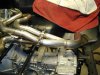
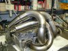
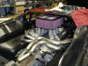
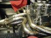
Here are some build pictures of the seven merge collector system that I built for my Pantera back in 2000. The seventh collector combined everything into one with a megaphone for track days. For street use the last merge is replaced with two mufflers. As has been said, the tube lengths are not optimal but they are within .25" of each other.
Attachments
great system
This is exactly what i thought of. Also here some questions
Which cylinders are paired into 8- 4 -2 headers ? ( can´t see it exactly on the pictures)
What where the results ( hp, torque) compared to a 180° Crossover system with a 8 - 2 design ?
What is the difference in performance when you add the seventh collector ?
BTW great welds and workmanship ( i used to work as a dairy engineer, so i have seen a lot of welds )
TOM

This any use Jac?
Keith that is the same as the Schematic ( Colour coded ) I posted of Adam C's. These are for 180° 'normal ' GT40 etc.
Tom wants the cyl pairings for 360° intervals & 4 tailpipes.
That would be---1-6, 5-3, 4-7, 2-8, these would need to be arranged so that 1647 could be brought into one tailpipe & 5328 in the other for comparitive testing so on the car you would want to arrange them in a sequence that allowed this.
Jac Mac
Similar threads
- Replies
- 0
- Views
- 299
- Replies
- 1
- Views
- 582
- Replies
- 5
- Views
- 662
- Replies
- 4
- Views
- 978