Question on Fitting Performer Heads

Dave Bilyk

Dave Bilyk
Supporter
I just bought a pair of Edelbrock Performer heads, (1.9" so no worries with pistons) manifold and roller rockers. My engine is stock, and installation looks reasonably straightforward, but since it is not many weeks to the Lemans classic, I dont want to take any undue risks.
So my question is; are there any risks or issues that I should be aware of?
If you guys can help me decide whether to fit now, or leave until after Lemans that would be great.


Dave
 

Randy V

Moderator-Admin
Staff member
Admin
Lifetime Supporter
Dave,

Good move!

* Make sure you get headgaskets that are compatible with the alloy heads.
* Pay the extra money for ARP Studs and the correct washers as most alloy heads for SBFs are setup to work with 1/2" bolts/studs. The washers will adapt to the 7/16" fasteners.
* Make sure you check your push-rod length - I've found that in the majority of cases the pushrods from the factory are not the optimum length.
 
I have the same heads on my car, as Randy says the gaskets can't be standard items as the alloy will attack the metal on them. When I assembled my engine I fitted a head and used a bit of plasticine stuck on top of the piston just to check clearance - I have plenty of clearance with 1.6 rockers and could more than likely go to 1.7 with no probs later on. Another point is that they have small holes at the ends of the heads I think for emmissions and these need to be blocked with bolts or the fittings that come with the heads.
 

Neal

Lifetime Supporter
If they have EGR ports on the back (flywheel side) be sure to plug them.
 
Dave, To be absolutely sure you have no clearance issues, Fit two very light checking springs to two valves on any one cyl, temporarily fit the head minus head gasket and install with pushrods / rockers to those two valves only. Adjust valve lash to zero with pushrod cup of lifter up against circlip. Now rotate crank approx 20° at a time- at each of these points check the pushrod cup is up against the circlip in the lifter and that the valve can still be pushed open further by hand. Continue to do this on both valves every 20° until you have completed two complete revolutions of the crankshaft. If at any point the valve cannot be pushed further open by hand ( There will be a couple of points where clearance may be as low as 2mm / 0.080" ) stop & remove the head to investigate why. If all goes well then you are assured of having approx 3mm/0.120" valve to piston clearance once assembled with the head gasket ( probably more depending on other clearances.

Some 'bearing blue' applied to valve head prior to check will make it obvious where contact points are-- try to limit your hand pressure opening checks to around 2mm/0.080" to avoid any confusion in marks.
Only by doing this can you be absolutely sure of no valve contact problems.
 

Dave Bilyk

Dave Bilyk
Supporter
Thanks guys.
Randy, head gaskets are Fel Pro 1011-2 as recommended by Edelbrock.
7/16" ARP head bolts with Edelbrock bushings.
Will check pushrod length, new standard length hardened steel pushrods.

Paul, I have 1.6 ratio roller rockers, so for now with the standard cam, I don't forsee any problem, but I will check clearance. The other thing I might need to do is change the rocker covers, I am not sure that my Ford Racing covers will clear the roller rockers, so thats another check to make.
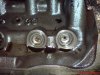
Emission holes noted, will check.

Neal, thanks, will check, but I think I read that these are non EGR heads, and the EGR heads are a different part.

Jac Mac, ok understood, seems a well thought out method.

The only other thing I was worried about was the clearance between exhaust and rocker cover is only about 1" on one side, so if I need a larger valve cover it might get closer. I will check everything over the next week. Fitting a radiator at the moment, and am making brackets to weld on to the chassis, so if I can finish in good time, I will have a go.

btw, I ordered heads, rockers manifold, bolts and gaskets from Roadcraft Repower suppliers of American engine parts from Edelbrock for Ford and Chevrolet V8 engines and Tremec transmissions at lunchtime monday, arrived tuesday. The site is well laid out and easy to find stuff, with plenty of explanatory notes, so it gets a thumbs up from me. I have no connection with them, but they were helpful when I phoned and checked that I had ordered compatible parts. The heads seem a good price too, so if you are thinking of buying heads check them out.

Dave
 

Dave Bilyk

Dave Bilyk
Supporter
So far so good, I got the iron heads off, everything looks fine, cleaned up and test fitted one ally head, but found that without the gasket (no pushrods in) there was a slight interference as at least one piston is 6 thou above the deck at TDC (will check the others tomorrow).
So I used some pieces of 15thou gasket to give clearance, then fitted two pushrods and checked for freedom of rotation and measured valve lift which was just over 3/8" . I havent got a valve spring compressor yet to check valve to piston clearance by your method JacMac, I may try plasticine.

regards
Dave
 
As far as head bolts goes, ARP makes head bolts specifically for Windsor applications with aftermarket heads that are the 'whip-daddy'. Apparently stock heads use a 7/16" bolt size, whereas most aftermarket heads are set up for 1/2". Most people just use a sleeve or spacer to secure the heads with standard-size bolts, which is a compromised solution that can potentially allow the heads to walk around a bit on the gaskets.

But ARP makes special stepped bolts that have a 1/2" shank to fit properly on the heads, and a 7/16" end to thread into the block. They are rather proud of these bolts, as they sell for $123.99 from Jegs:

ARP 254-3708 - ARP Professional Series Head Bolt Kits - JEGS

The ARP catalog lists them without giving much detail. I bought them for use with my AFR heads, and my engine builder (who was with Roush for 25+ years) was amazed, as he'd never heard of them before. He pronounced them excellent, and perfect for my application.

Interestingly, ARP lists the following for use with certain Edelbrock heads:

FORD, SMALL BLOCK
289-302 standard, Edelbrock head 60259, 60379: 6-point: 154-3601 12-point: 154-3701

From this I assume that these Edelbrock heads use the standard 7/16 bolt size?
 

Dave Bilyk

Dave Bilyk
Supporter
Mike,
the holes in these Edelbrock heads are for 1/2" bolts, and the stock is 7/16" as you say. Edelbrock sell spacers to mate the bolts to the heads. Interesting that you can get the 1/2" bolt with a 7/16" thread. Edelbrock say that for mild cams and compression ratio 7/16" is ok, but for high compression and wild cams, you should go to 1/2".


Most people just use a sleeve or spacer to secure the heads with standard-size bolts, which is a compromised solution that can potentially allow the heads to walk around a bit on the gaskets.

Remember that there are two dowel tubes which control the head location onto the block, so this is not really an issue.

regards
Dave
 
Before ARP arrived on the scene I simply drilled & tapped the 302/289 Blocks & Heads out to 1/2" UNC & used the 351w bolts. The xtra dia & 100ft lb torque along with 'posting' cured most of the Headgasket problems on race setups. You guys dont realise how easy you have got it these days.:)
 

Randy V

Moderator-Admin
Staff member
Admin
Lifetime Supporter
Before ARP arrived on the scene I simply drilled & tapped the 302/289 Blocks & Heads out to 1/2" UNC & used the 351w bolts. The xtra dia & 100ft lb torque along with 'posting' cured most of the Headgasket problems on race setups. You guys dont realise how easy you have got it these days.:)

My only concern about doing that Jac is that the decks on many (most late) 302 blocks is very thin and the cast boss that accepts the head-bolt in the deck is very small in diameter..

I consider Ford's move to just 4 - 7/16" headbolts per cylinder along with a substandard gear cam/distributor gear interface to be to two largest engineering screw ups they have ever made..

That said - I have not experienced any problem with the heads walking on the block - that's typically taken care of by the locators / alignment sleeves that are installed in the block prior to installing the gasket and head.
 

Dave Bilyk

Dave Bilyk
Supporter
Hi Brett,

quote from the installation instructions sheet that came with the heads;
" It is recommended that 289 - 302 engines producing 380 or more horsepower (or with nitrous oxide) be converted to accept 1/2" diameter bolts by a qualified machine shop to ensure maximum head gasket durability."


regards
Dave
 
Randy, I agree that the later model 302 production blocks are a probably an exception when it comes to drilling out to accept 1/2" bolts/studs, the early split rear seal type blocks have more material in this area. Actually when it gets to the point where 1/2" hardware is reqd on one of the later blocks its time to reconsider your options and buy a race type block with sufficient strength/material for the purpose you have in mind;eg- main webs, cyl wall thickness, priority oiling.
 
I consider Ford's move to just 4 - 7/16" headbolts per cylinder along with a substandard gear cam/distributor gear interface to be to two largest engineering screw ups they have ever made..

Cant let this one go Randy- I worked in a Ford Dealership from 67 thru 72, then did nothing bar chev/fords in an engine import shop til 79. The only-repeat only dist gear failures were due to one of the following causes- crap getting thru the by-pass hole in the pickup screen and literally jamming the oil pump- seized distributors due to infrequent oil changes.

Most if not all other failures are caused by aftermarket or ill conceived modifications- Hi Volume oil pumps, camshafts made from different materials with little thought to compatibility with the distributor gear,new gears fitted at the wrong height on the shaft which either causes the gear to eat into the block when the dist is fitted or the shaft in the dist to be pulled down into the housing if there is too much clearance, or just plain stupidity on the part of operators who think 5000 rpm is a good idea on a cold engine. So really all the problems have been 'caused' by the Hot Rod-go faster community .

The 4 bolt around each cylinder is not really the problem either, its the thin wall casting tech adopted by the manufacturers and further implementation of that reqd by the company bean counters that has reduced the rigidity needed in the cylinder head/block to maintain a flat sealing surface.

Sorry for the slight drift Dave!
 
Hi Dave

Regarding Performer Head fitting you could look up David Champ's website via the GT40 Enthusiasts Club website. Dave patiently and thoroughly logged the entire procedure during the engine build of his car. I have now owned the car for nearly 2 years and touch wood the engine is running well.

Hope this is of assistance to you.

John
 

Dave Bilyk

Dave Bilyk
Supporter
No drift here JacMac, it's all interesting and on target.
btw, three or four of the pistons are a few thou proud of the deck at their TDC, plasticine shows sufficient clearance, so I will continue the build tomorrow (day off).
Also, noticed that the outer head holes in the block go through into the water jacket, and the builder had used some ptfe tape in the upper part of the bolt thread to help seal them. Is that a standard move?

Thanks John, I'll have look at Daves site.

regards
Dave
 
Those outer bolt/threads require a pliable non hardening sealant. I use Loctite #3, pn 30517. # 2 pn 30514 has the same properties. These are for bolts. There are plenty of other suitable sealants as well & Im sure everyone has their favourites!

For Studs in this application follow the suppliers directions while bearing in mind your particular cylinder block with some blind and some open holes.
 

Randy V

Moderator-Admin
Staff member
Admin
Lifetime Supporter
Cant let this one go Randy- I worked in a Ford Dealership from 67 thru 72, then did nothing bar chev/fords in an engine import shop til 79. The only-repeat only dist gear failures were due to one of the following causes- crap getting thru the by-pass hole in the pickup screen and literally jamming the oil pump- seized distributors due to infrequent oil changes.

Most if not all other failures are caused by aftermarket or ill conceived modifications- Hi Volume oil pumps, camshafts made from different materials with little thought to compatibility with the distributor gear,new gears fitted at the wrong height on the shaft which either causes the gear to eat into the block when the dist is fitted or the shaft in the dist to be pulled down into the housing if there is too much clearance, or just plain stupidity on the part of operators who think 5000 rpm is a good idea on a cold engine. So really all the problems have been 'caused' by the Hot Rod-go faster community .

The 4 bolt around each cylinder is not really the problem either, its the thin wall casting tech adopted by the manufacturers and further implementation of that reqd by the company bean counters that has reduced the rigidity needed in the cylinder head/block to maintain a flat sealing surface.

Sorry for the slight drift Dave!

With Dave's permission... :)

Regarding the gear interface - I agree completely that the interface is sufficient for "normal" use when the appropriate material gears are used. However, unlike virtually all other American mfgrs, the design leaves precious little margin for error or abuse. Certainly the implementation of steel billets for roller cams in the mid-late 90s has played a HUGE roll in the failures since many of the aftermarket mfrgs of distributors went clueless for many years and let the consumer (and their mechanics - us) worry about why their distributor gears failed.. There are plenty of applications where I (as an engine builder) would like to have the additional oil flow capacity of a high volume pump - but instead and forced to the standard volume units. I care nothing about the high pressure units in any case.

RE: 4 bolts per cylinder - I agree. However - there was NO excuse that Ford could ever give me that excuses them for using a cheesy little 7/16" fastener for a 4 head-bolt system. Chevrolet - as I'm sure you are aware - used 7/16" headbolts as well, but there were 5 of them per cylinder.

RE: Thread sealants - I prefer to use a Teflon paste thread sealant on all the headbolts and a drop of oil on the bolt seats of each in order to get consistent and accurate torque readings..
 

Dave Bilyk

Dave Bilyk
Supporter
Finished installing new alloy radiator today, so heads back on tomorrow.
Just reading up on lifter adjustment, I think I have hydraulic lifters, based on the fact that there appears to be an inner part retained by a wire circlip. From what I have read, the aim seems to be to preload the lifters by 1/2 a turn or by a torque such that they dont clatter, yet allow the valves to close fully.
With the stock valve train there seems to be no adjustment. I have heard of these things 'pumping up' at higher revs, so could they have been a potential cause of the misfire I experienced above 5500rpm?


Dave
 

Attachments

  • gt40 007w.jpg
    gt40 007w.jpg
    69.5 KB · Views: 359
Back
Top