Roaring Forties 105

These are the new wheel centers for the 15" rims.
I was given a raw casting of a Halibrand( I thank RF for that) and I had it modified by a pattern maker.
I had meat put in around the center so I could machine more out of the back without the drive pin holes braking through the front.
I had a 2 spares made just in case.
I ordered the rim sections today.
 

Attachments

  • DSCF0014.JPG
    DSCF0014.JPG
    41.9 KB · Views: 521
  • DSCF0015.JPG
    DSCF0015.JPG
    39.6 KB · Views: 528
Last edited:
Steering arm and beer.
Problem solving is easier with beer.

Dave I can taste it I can smell it I can feel it
 

Attachments

  • DSCF0023.JPG
    DSCF0023.JPG
    40.6 KB · Views: 548
There has been hours and hours of sanding in the bodywork dept.
Adding and subtracting, I have gaped the body and it is pretty much done.
There will be a little more detail work, I will not paint it till I get # plates on it,while it is in primer I don't have to be careful.
 

Attachments

  • gt40-001.jpg
    gt40-001.jpg
    35.1 KB · Views: 578
In Australia and particularly the State of New South Wales has a very tight Emissions regulation if you choose to go down that path.

My advice is don’t.
Put an Aust eng less than 3 years old with original ECU and be done with it.

You can use a USA eng going back to certain dates ect ect.

And RF has a factory option as well.


But there is a 10 year rule on engines after that you require an emissions test(IM240) as well.
As we are building a new car 2009 then you pass the 2009 emission test.My engine is 96 model engine.
Very very hard.

I was caught by this 10 year rule due to the build time.
I had reservations that the 96 ECU would pass current emissions so an Autronic was fitted.

The friend that tuned the car I have to thank for the hours he put in.
Thank you Jake.

We both went in blind and anxious at the outcome.
There were a few things against us compression was higher in 96 eng.
Cam larger and intake manifold was a different design.

I took the car to a dyno manufacturer who had an IM240 simulation , we then spent hours setting up what we thought was close.
One of the issues is the RTA test in grams per KM GPKM and all workshops measure in Parts per million. PPM.
So after the 1st dyno session I took the car to the RTA and got the figures.
Then looked at how much we failed in percentage GPKM.
Then looked at our 5 gas curtain area figures and tuned to the required percentage drop to pass or better.

We both learnt a lot about gasses over the period of several dyno sessions.
The car covered 400 KM over the period .
This is the short story 3 days fabrication and 30+ hours of dyno work


We passed on the 2nd go Yee Haa .
I am not going back down that road,take the easy road and fit a late model engine.

Wheels ,Tyres ,engineering and RTA then paint.
Next time you guys see her she will be octane orange with a white strip.

Jim
 
Last edited:
Its been a while since I looked at your log Jim, fantastic effort as usual. When are you going to knock up a set of solenoid operated valve heads mate? Just a little finishing touch.

Fred.
 
Been a long time since I updated my build page, almost 3 years.
It took around 18mths to get the car through the RTA with their back and forth bullshit games.
Eventually Trevor Booth and I got it done.
I have done about 5000km on it 2.000 would be track miles.
I did a several days sorting suspension and I am very happy with the way it handles.
I found once the car is on the road you make a few changes just to hone the ergonomics such as vision ,ventilation , I remade the side windows as I found the the others I had made were clumsy to use.
All the garb on the TB is what I posted in the induction forum months ago.
The TB have not missed a beat, the only mod was to the cable wheel /TPS mount it required a throttle stop and its own spring as it was causing inconsistent readings and idle speeds.
Apart from that it has been ultra-reliable
In fact the whole car is ultra-reliable even at the track days I don’t get mechanical issues.
I did brake one of the extractors of because and eng mount split and the eng sat down lower and the pipe was on the chassis.
I have since remade the brackets to house a different bush.
 
I decided to make an 8 stack for my 96 cobra modular engine.

I didn’t want to buy one because that goes against the grain.

The engine I have has a split port design, in one port it has a second set of butterflies this has been programmed to come on at 4.500rpm, the factory turns it on at about 3.500rpm.

The job of fabricating the lower section was deemed as to time consuming for the minor benefits if any that I may have been able to get.

The injectors are in the secondary throttle plate and this was also a factor as I wanted to retain their location as well as the secondary butterflies.

I gave up looking for a factory manifold as it seemed impossible here in Aust.
But one came up on fleebay about a month ago so I’m into it.

The first pic is the factory manifold with the top hat and throttle body taken off, it exposés the runners inside the plenum.

I attacked it with an air hacksaw to get the majority out then set it up in the mill and machined out the remainder.
 

Attachments

  • tb1.jpg
    tb1.jpg
    3.6 KB · Views: 358
  • tb2.jpg
    tb2.jpg
    2.8 KB · Views: 282
  • tb3.jpg
    tb3.jpg
    4 KB · Views: 348
Last edited:
After machining out the remainder I then had the measurements for the second stage.

I used 10mm alloy plate as I don’t want the t/bodies to move around .

Drilled and tapped holes for the throttle bodies to mount to.

I used the original ford gasket as it very good.

I counterbored the holes for the bolts that mount the plate to the manifold base as they will foul the t/bodies.

I was very nervous at the last hole because their is really no room for error when it all comes together
 

Attachments

  • IMG_0023.JPG
    IMG_0023.JPG
    211 KB · Views: 280
I worked out some port area ratios, the valve size is 37mm each ,that makes it about 52mm if it was 1 valve.

The entry in the port at my counter bore in the factory manifold is 45mm, that makes it about 86% STD so I’m not playing with that.

When we use the open port it has a ratio of 72% that is why it has good pull down low.
When the secondary port opens and the 2 are in use it is 97% which is way to big but it seems to work for it.
The secondary b/flies are either on or of but I am going to look at working something out at a later date to step it as required to get more out of it.

Tapered tube to meet port to plate,the tubes will be o'ringed but I have not had a chance yet.

The 1st pic is of the ports on the exit of the manifold
 

Attachments

  • IMG_0031.jpg
    IMG_0031.jpg
    3.1 KB · Views: 271
  • IMG_0067.jpg
    IMG_0067.jpg
    3.2 KB · Views: 266
  • IMG_0069.jpg
    IMG_0069.jpg
    2.9 KB · Views: 267
Last edited:
I decided on 48mm TB due to their location in the port and. the length is going to governed by the back window unfortunately ,I am chasing about 15 " from the valve seat but I may end up shorter ,thats life.

The ID of the trumpet is 55 at the entry which is just over the valve size.

I already had a body design in my head so that was straight forward.

The best thing I made was this jig.
I take the jaw out of the vice and bolt it in then datum of and plough through the process's.

It does seem to go on forever at stages but you just keep going.
 

Attachments

  • IMG_0052.jpg
    IMG_0052.jpg
    3.7 KB · Views: 300
  • IMG_0053.jpg
    IMG_0053.jpg
    3.9 KB · Views: 264
  • IMG_0055.jpg
    IMG_0055.jpg
    4 KB · Views: 278
--------------------------------------------------------------------------------

Going for 8TB was my option due to bore spacings and also I want to open the BF to favour the open port not the closed port ,I cant do that with a webber style setup.

The shafts I did buy and cut them in half.
The shaft were a pain in the arse,they stress relieve after they machined the slot I think
.The amount of dicking around to get them right was painful.
I machined flats to suit using the BF as a datum plane.

The linkages I did on the cad to get a even sweep from close to open, I put flats on the shaft section to get indexing and a positive lock on the shaft.

Machined ss spacers with grubs and put them together on a jig.
Made a posts for the idle screw to mount into it also doubles as a throttle stop
 

Attachments

  • IMG_0060.jpg
    IMG_0060.jpg
    3.6 KB · Views: 259
  • IMG_0061.jpg
    IMG_0061.jpg
    3.7 KB · Views: 260
  • IMG_0062.jpg
    IMG_0062.jpg
    3.4 KB · Views: 250
  • IMG_0063.jpg
    IMG_0063.jpg
    3.1 KB · Views: 222
made delrin sleeves for the coil springs to live on.

Starting to get to the dummy up stage.
 

Attachments

  • IMG_0059.jpg
    IMG_0059.jpg
    3.4 KB · Views: 301
  • IMG_0065.JPG
    IMG_0065.JPG
    4.2 KB · Views: 315
  • IMG_0070.jpg
    IMG_0070.jpg
    3.6 KB · Views: 302
Last edited:
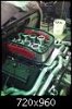
I still haven’t painted the car because I have been toying with ideas for the body.
One of my passions is panel forming, I’m no master at it but I have a handle on how to go about it, over the years I have accumulated equipment and have played with small jobs in areas but nothing big ,door skins boot lids ect ect.
I was going to make my next project a P4 with alloy body and have already got the ground work started on that but I thought it would be good practice in a few areas of making forms/patterns and technique to use the 40.
Its moving fast so I will post as I go on the project as I progress.


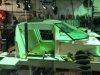
I have to make the cock pit first as you need a datum for the whole car to start from.
As the front /rear clip mount to this it is the datum for those sections

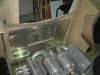
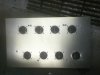
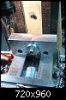
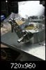
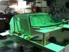
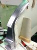
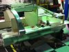
The first stage was to make a form.

This was made out of 16mm ply, I used a laser to strike a line across the back of the pontoons, this was my datum to get measurements forward to the fire wall/front screen top and bottom.
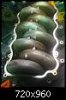
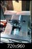
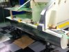
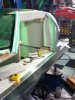
I purchased 4 wood working profile gauges and linked them to get the profiles of the roof ect ect.
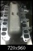
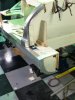
The form was then put together checking measurements of the car.
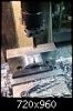
I have only measured and profiled of one side of the car to make it symmetrical.
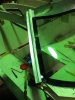
The form took approximately 3 working days to make.

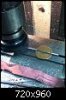
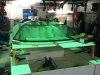
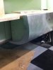
The form has been added to since these pics were taken ,you keep adding to give you the acuracy required for panel fit and manufacture, the form is a jig.
Jim
 

Attachments

  • IMG_0018.JPG
    IMG_0018.JPG
    276.7 KB · Views: 425
  • IMG_0019.JPG
    IMG_0019.JPG
    321 KB · Views: 422
  • IMG_0020.JPG
    IMG_0020.JPG
    286.4 KB · Views: 358
Last edited:
I wasn't going to make the sill's yet but I did any way.
The front and rear flanges I welded in on these because they are to wide to use the jenny on.
 

Attachments

  • IMG_0044.JPG
    IMG_0044.JPG
    246.4 KB · Views: 386
  • IMG_0045.JPG
    IMG_0045.JPG
    281.9 KB · Views: 397
  • IMG_0046.JPG
    IMG_0046.JPG
    234.6 KB · Views: 349
  • IMG_0049.JPG
    IMG_0049.JPG
    302 KB · Views: 389
Last edited:
Started playing with the A pillar and I think I have it worked out.
It a tough one because you have folds and it is compounding to follow the screen.

The test one I am reasonably happy with and may use it , there will be an inner shell that joins on at the flanges but I havnt made that yet as I only need the outers to mount the screen.
 

Attachments

  • IMG_0036.JPG
    IMG_0036.JPG
    285.2 KB · Views: 363
  • IMG_0057.JPG
    IMG_0057.JPG
    272.8 KB · Views: 353
Last edited:
Back
Top