
Can anyone suggest where i could find a suspension utilizing unequal length a-arms and rod end bearings, for a mid engine car weighing around 2000 pounds with 500 horsepower/G50 trans? I know this is a broad subject and a very general question but i've poked around quite a bit and havent been able to find exactly what im looking for. I've been planning on using corvette c5 suspension, ala factory five gtm, but im having a few interference problems in the foot box because of the shear size of the cast aluminum a arms, and im not too keen on using rubber bushings or having to convert it to coil over shocks and springs. So basically im looking for something similiar that is more compact in its a-arm design that would utilize simliar geometry and rod end spherical bearings. Was thinking about using c5 uprights and fabricating a arms myself but id like to avoid having to weld a arms. Was looking at viper suspension components as they are more compact in their a arm design and already use coil overs shocks/springs but they still use rubber bushings. Not building this thing for comfort! Thanks for reading this and any ideas would be greatly appreciated!

You are using an out of date browser. It may not display this or other websites correctly.
You should upgrade or use an alternative browser.
You should upgrade or use an alternative browser.
suspension ideas?
- Thread starter billium01
- Start date
Bill,
Welcome to the dilemma. Footwell size versus wishbone lengths has always been a sticking point in cars with a wheelbase such as that in a 40 or other short wheelbase cars with similar dimensions.
I think the Corvette parts are really good, and some awesome brakes can be fitted to them as well, but to fit them to your chassis you will need to strike a compromise between footwell width and wish bone length while maintaining geometry that makes the chassis work.
I would say a good compromise would be a tapered footwell with custom made wishbones that provide your adjustability.
Your suspension components will be appreciably shorter than stock but your overall travel will be less so its easier to get things working and solve issues like bumpsteer.
The upper arm will be shorter by virtue of the upper ball joint placement and you will have some camber gain but not a lot is necessary as chassis roll is not as severe as in a heavier and taller chassis with a high CG.
I would get to a good chassis guy in your area and have the whole setup laid out after you have a comfortable footwell and I would bet that with a modest investment you can get pieces fit to your chassis that will accomplish what you want.
Good luck with your project
Phil
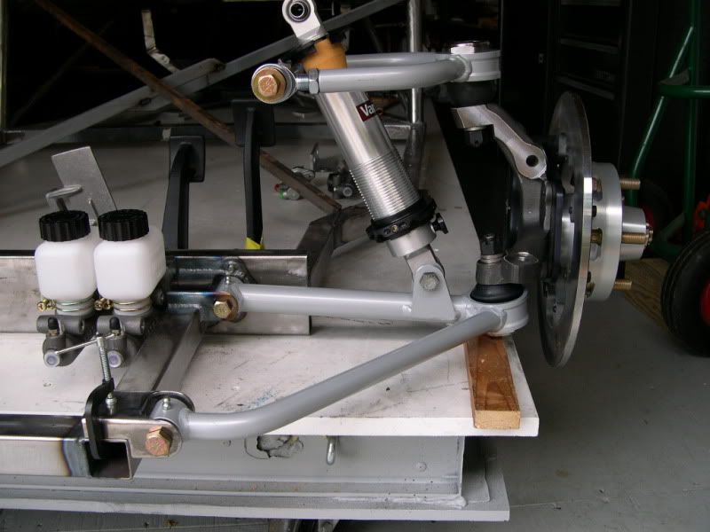
Here's mine...

Its all in front of the foot box, so no issues with that and I think the weight distribution is going to come out at 40 front -60 rear and the wheel base is ~102" which is not too long I think, so it can be done.
Just keep working at it and you'll get there.
Check out my site, it might give you some ideas on a few things...
http://guerillamotive.com/wordpress/
Thanks for the input fellas. The way i have it designed now, I have three inches of suspension travel before the front a arm would touch the bottom frame rail of the foot box. Think I'll have to redesign the foot box or the a arm to get more clearance.
Attachments
Alot of you designers give up foot room by using a certain design of A arms. Let me explain. The standard lower and upper A arms splay both forward and rearward of the tire centerline. This immediately reduces the cockpit size as you have to allow for the arm as well as the tire turn radius. The ford big car lca,s that extend out from the chassis perpendicular and use a forward running strut free up room behind the tire centerline. The effect at the upper arm is lessened because its "footprint" at the chassis is usually smaller. However the upper A arm can also be designed this way and still maintain all the geometry of any other system. You now have no suspension components that are behind the centerline of the front wheel.
Well technically there are a few pieces that are a inch or so behind centerline when you factor in caster.
Well technically there are a few pieces that are a inch or so behind centerline when you factor in caster.
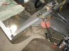
Using a forward canted lower A-arm might help? The ones in my build are designed to support an iron V8 sitting right on top of them, so should be plenty for a lightweight mid-engine build. I spend a considerable amount of planning time trying to figure out how to fit an A-arm where my feet needed to go! As you can see from the pic - the lower bulkhead piece forms the rear LCA mounting point, as well as the front side of the MC mounts. This is an early mock-up pic before the upper chassis structure was built - I'll be completing the upper A-arm mounts this Spring.
Yes nice work Jeff! In your design how about alignment issues as far camber caster and toe? Will they be adjustable? Ive noticed some designs that allow for that and others that dont. Just wanted to clarify one thing as well. Finding room for the wheels to steer hasnt been a problem. My problem lies in the bump stop area of the lower a arm. In other words under full compression my a arm might touch the frame! not good for sure!Using a forward canted lower A-arm might help? The ones in my build are designed to support an iron V8 sitting right on top of them, so should be plenty for a lightweight mid-engine build. I spend a considerable amount of planning time trying to figure out how to fit an A-arm where my feet needed to go! As you can see from the pic - the lower bulkhead piece forms the rear LCA mounting point, as well as the front side of the MC mounts. This is an early mock-up pic before the upper chassis structure was built - I'll be completing the upper A-arm mounts this Spring.
Hi Bill,
Those C5 parts are very detailed models, where did they come from? Your own work?
How close together are your seats? It looks like you only need to drag in the bottom about 3" then the arm would clear. Pushing your seats together as much as possible might give you the room.
I found with fitting myself into the car that the CAD model had limited use to get the ergo's sorted. I built an MDF mockup of the cabin and that helped a lot. In my case my I made the thing far too narrow which became imeadiately apparent when I went to sit in it.
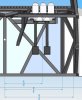
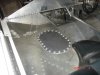
The attached picture shows a few dims from my car:
From the CL of the car to the CL of the steering wheel 322mm.
From the CL of the car to the narrowest part of the foot box 495mm.
From the CL of the car to the regular chassis width (it gets a few mm wider as it goes back) 590mm.
Note: I know the throttle pedal is missing but I'm sure you can see there is plenty of room for it.
Those C5 parts are very detailed models, where did they come from? Your own work?
How close together are your seats? It looks like you only need to drag in the bottom about 3" then the arm would clear. Pushing your seats together as much as possible might give you the room.
I found with fitting myself into the car that the CAD model had limited use to get the ergo's sorted. I built an MDF mockup of the cabin and that helped a lot. In my case my I made the thing far too narrow which became imeadiately apparent when I went to sit in it.
The attached picture shows a few dims from my car:
From the CL of the car to the CL of the steering wheel 322mm.
From the CL of the car to the narrowest part of the foot box 495mm.
From the CL of the car to the regular chassis width (it gets a few mm wider as it goes back) 590mm.
Note: I know the throttle pedal is missing but I'm sure you can see there is plenty of room for it.
Attachments
Thanks for the compliments guys.
Bill, the LCA is fixed in position, but the UCA has lots of adjustability. It will mount to a removable plate (not shown) that will allow for about +/-2 deg. of caster adjustment via slotted mounting points. Camber is easy to tweak with the UCA rod ends, as well as a little bit of caster fine tuning too. The mounting plate allows for lots of variety of different positions of the UCA inner mounts, including anti-dive by just making a new plate.
I wanted to use off the shelf parts as much as I could - these are Alston's Chassisworks parts with some modifications. I altered the UCA a little to tweak the RC vertical movement control. My planned geometry has pretty good RC control in bump & roll, with about 0.5deg camber gain/inch, fairly long VSAL and low RC static height. Hopefully it will work as good in driving as it does on paper! :thumbsup:
Toe is the easiest with the tie rod ends and standard rack adjustments. My bump stops are the Koni bumpers adapted to the Chassisworks shocks. If you're concerned with bump control you might want to consider positive bump stops added to your design (with some compressible bumpers) - you don't want metal to metal!
If I were to build it again - I'd consider Wilwood's new spindles, along with some Speedway Motors "modified" control arms. These would allow for improved/easier adjustability.
Jeff
It doesn't really say if you are building a GT40 or not, but the first conclusion I came to when I began my design, was the fact that the C5 Uprights won't work with the authenticly backspaced 15" wheels. So you wiould have to make concessions (17" wheels, different offset, etc). This is why I chose to use C4 fronts.
Darnel
Darnel
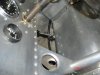
This has been noted before, but you don't absolutely have to keep suspension arms out of the cockpit entirely.
Have a look at the front lower control arm rear inner pivot on a friend's M12 Mclaren canam car. Its directly beneath the driver's right leg.
Jack
P.S. Where can I find out more about Wilwood's new spindle?
Have a look at the front lower control arm rear inner pivot on a friend's M12 Mclaren canam car. Its directly beneath the driver's right leg.
Jack
P.S. Where can I find out more about Wilwood's new spindle?
Attachments
Wow - I guess that's one way to do it, but the mind wonders to where you'd be "taking" that control arm in a front ender! My idea was to keep the suspension out of the footbox as much as possible (for physical room and safety). I love Can Am cars and have spent countless hours studying suspension designs they used. Lots of innovation there!
For a higher end spindle option one might consider the ATS spindles (from the pro-touring guys).
T56Kit.com, Home of American Touring Specialties!
I know the good folks capabilities here range from adapting a mass production car piece - to casting and machining their own custom design uprights! That's a BIG difference in cost and capabilities.
In my case, I didn't want to overbuild for the planned weight and intended use of the car, which is all to easy to do given the front weight bias of most mass produced cars. Other consideration we're aftermarket support, ready availability, expense and geometry considerations.
While the old M-II spindle (IMCA versions in my case) aren't perfect, they were the best fit for my criteria and carefull planning gave me some decent RC and geometry control to boot. :shy:
The suspension pieces in my cad drawing were given to me by a friend of mine. He had the actual parts 3d scanned. Unfortunately he gave them to me with the explicit instructions not to share them. :sad: Being a man of my word, well there it is. The car itself is not a GT40 but one of my own design very loosely based on a porsche 908/3. It'll be a spyder because making custom dot safety glass is very expensive. Dont want it to be a trailer queen either and i thought having the wind in your hair would add to the experience. At least for the first 50 miles! Not building this thing for comfort though, just performance. I think to get the clearance i need for the lower a arm, I'll just have to make a jig and fab them myself. I really like Jeff's UCA mounting plate idea for front geometry adjustability. Thanks for everyones input!!
Similar threads
- Replies
- 4
- Views
- 948
- Replies
- 16
- Views
- 2K
- Replies
- 0
- Views
- 600