Two way fuel valve ?

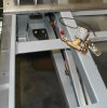
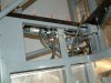
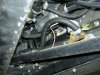
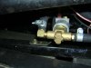
Hi , I am getting some of my fuel system in order and cannot find the locaton for mounting the 2ea. Two way fuel valves. I cant find them in the manual. In the other manual (electrical) it states under the Main Body Harness file "2 way valve: Black/Orange - eyelet terminal " . I grabbed the main body harness , traced it down along with the lead for the low preasure pump . From this it looks like the two have to be within 6-8 inches from each other which gives me a idea of placement. Does any one have a picture of where they placed theirs ? Also as the manual states and the way the harness is set up it has a eyelet terminal on the wire to the valve. The valve has a male spade connector on it for the B+ harness and a ground strap with a eyelet.That doesnt match the harness , am I missing something or is it just set up wrong ? Thanks for the help , Dan /ubbthreads/images/graemlins/crazy.gif
 

Attachments

  • 50724-P1230002a.jpg
    50724-P1230002a.jpg
    45.5 KB · Views: 400
Well I looked at my manual today at work,,haha and realized I was confused /ubbthreads/images/graemlins/crazy.gif with the 3 port , 2 way return valve, ok that solves that part ,But still need to know where these 2 each valves are mounted in normal fashion, I'm guessing to the inner stainless side panels ??
 
Thanks Pat, maybe they go to a water fountain in RF's shop and they accidentally fell in my shipment ! I guess Robert will chime in when they reopen from their January vacation.Any other RF builders or Hersh know anything about them ? I thought they go between the main tanks and the filter/low preasure fuel pumps.They were packaged with my pumps and all the fuel fittings. Thanks for chiming in Pat. /ubbthreads/images/graemlins/grin.gif
 
Dan,
I don't get to check in here as often as I used to. If you post a question here and you don't get a response in a day or two then please send me an e mail. I will do what I can to solve the issue.
Those are fuel shut off selinoids. They are put in line in front of the low pressure pumps to keep fuel from being pumped backwards through the system. The wire plugs into the same connecter that the low pressure pump does. That's why you have the three way shovel connecter. Then the ground wire goes to the same place as the LP pumps ground wire. What happens is that when you click the switch on the dash it opens upen the selinoid valve and turns the LP pump on at the same time while closing the other selinoid and shutting off the the LP pump.
Installing them is fast and simple. I will try and post a photo as soon as I can locate it. Ever sense my computer went down I've had to locate the old CD that the photos are stored on and locate what I need.

Hersh /ubbthreads/images/graemlins/smile.gif
 
Thanks Hersh, you said "They are put in line in front of the low pressure pumps " so they are in between the pumps and the tank right ? Just so were on the same page,,haha I thought that is where they went, If you can post that pic it would be much appreciated. That way I know where I drill to mount them wont end up being in a spot that later gets me in trouble. /ubbthreads/images/graemlins/crazy.gif
 
Don't know if this helps, but this is how I did it.
 

Attachments

  • 50984-DSCF0025.JPG
    50984-DSCF0025.JPG
    56.2 KB · Views: 429
Thanks Rolf, did you not have the valves I posted in the pic. above, cant spot them in your picture. Maybe this is something RF has since added ? Maybe Robert can chime in on that.
 
The device in your photo looks more like a low pressure pump. In my photo going from left to right you see the high pressure filter, high pressure pump, two way valve (mounted to the frame with two bolts), and towards the right hand corner the low pressure filter and pump.
 
Here are a few pictures of that valve the way it was installed on my GT. I hope they help.

Hersh /ubbthreads/images/graemlins/smile.gif
 

Attachments

  • 51285-Fuelshutoffvalve005.jpg
    51285-Fuelshutoffvalve005.jpg
    79.1 KB · Views: 377
If I am right it seems that the fuel system requires a backflow prevention valve installed between the tank and LP filter and pump to prevent fuel flowing back through the pump that is not running. When I was lookin at the manual in relation to the fuel system I wondered how this was addressed with the simple T connection that was shown. It should be noted that this backflow valve is not mentioned or pictured anywere in the manual.

In my build I decided to go with a six way valve that had seperate input and return lines for each tank. This removes any possablity of fuel flowing back into the incorrect tank without the addition of a seperate valve. The wireing of the valve also insures the operation of the proper LP pump.

This seems like a much simpler solution in what is an already crowded area. So my question is what am I missing? can someone point out the error in my logic before I sc**w up.
 
Back
Top