
RCR Auxiliary Instrument Panel
Chuck Schmidt
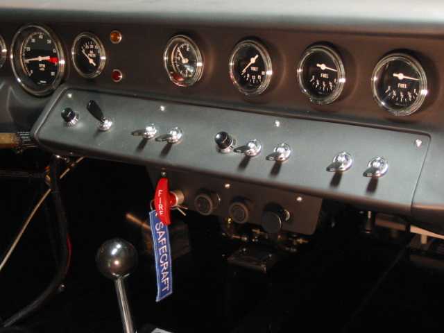
Adding a separate panel for heat, AC and fire suppression controls helps keep the dash clean and less cluttered on the RCR GT 40.
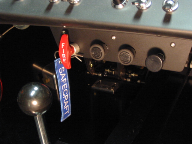
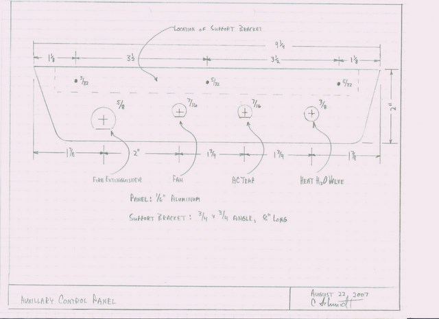
The air conditioning / heat unit has three controls: fan speed, AC temperature, and a cable operated heat control. A fire suppression system is being installed. The original GT had no air conditioning, so a location was sought other than the switch panels on either side of the dash to keep the appearance of the dash more original and less cluttered. A small panel, nine inches wide and an inch and a half tall, was fabricated out of eighth inch aluminum and secured under the dash, using an aluminum half inch angle bracket eight inches long. The panel was centered below the main switch panel. This ‘biased’ the location towards the passenger side to prevent interference with the driver’s right leg but yet looked appropriate. This extra panel is not obvious, but is easily seen and within convenient reach from the driver’s seat.
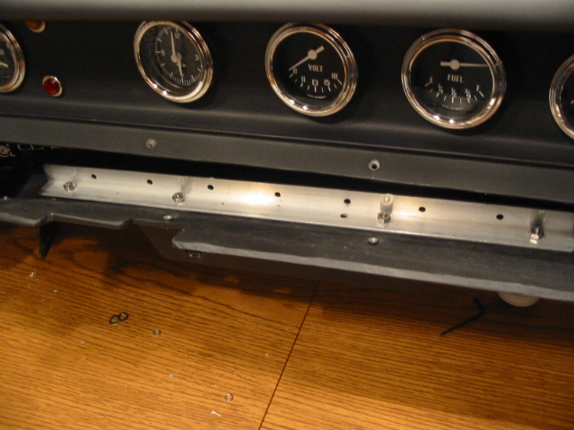
An aluminum half inch angle bracket, about twelve inches long was secured to the inside lower portion of the dash about three inches from the forward edge. This served several functions. First, it added some structural strength to the lower portion of the fiberglass dash. Second, it provided a backing support for the panel mounted below the dash. Third, eight holes were drilled along the vertical surface and three small bolts were placed to use as common ground points. Fourth, the remaining holes provided a good point to tie off the completed wiring harness making it secure and free from movement.
The panel was painted semi gloss engine black to match the rest of the dash.
Chuck Schmidt
Adding a separate panel for heat, AC and fire suppression controls helps keep the dash clean and less cluttered on the RCR GT 40.
The air conditioning / heat unit has three controls: fan speed, AC temperature, and a cable operated heat control. A fire suppression system is being installed. The original GT had no air conditioning, so a location was sought other than the switch panels on either side of the dash to keep the appearance of the dash more original and less cluttered. A small panel, nine inches wide and an inch and a half tall, was fabricated out of eighth inch aluminum and secured under the dash, using an aluminum half inch angle bracket eight inches long. The panel was centered below the main switch panel. This ‘biased’ the location towards the passenger side to prevent interference with the driver’s right leg but yet looked appropriate. This extra panel is not obvious, but is easily seen and within convenient reach from the driver’s seat.
An aluminum half inch angle bracket, about twelve inches long was secured to the inside lower portion of the dash about three inches from the forward edge. This served several functions. First, it added some structural strength to the lower portion of the fiberglass dash. Second, it provided a backing support for the panel mounted below the dash. Third, eight holes were drilled along the vertical surface and three small bolts were placed to use as common ground points. Fourth, the remaining holes provided a good point to tie off the completed wiring harness making it secure and free from movement.
The panel was painted semi gloss engine black to match the rest of the dash.
Last edited: