

You are using an out of date browser. It may not display this or other websites correctly.
You should upgrade or use an alternative browser.
You should upgrade or use an alternative browser.
suspension
- Thread starter brian snelling
- Start date
You have a PM
Brian,
This is the kind of questions that comes up now and then. Somone looking for a program that solves tha A-arm geometry lay-out. I would say that things are both more complicated AND easier at the same time. We can not just look for the "optimised" geometry, as we must clear out for what circumstances it should be optimiced for.
The moost tricky area is the front arm geometry. Beside the A-arm angle themselfs we have to deal with scrub radious and SAI inclinations, that create all kinds of negative effects that have to be compesated for with other allignment settings. Keeping those angles and distances clooser to zero makes for a moore easy car to tune. But it takes another front spindle that probabley has to be fabricated, more positiv offset wheels, loonger A-arms, relocation of the steeringrack etc etc.
When it comes to the A-arm geometry itself, we could shoortcut the discussion by saying that the forcelines should be keept low, using moore parallell and loonger A-arms, for a moore racing oriented car, and that the lack of camber copmensative geometry should bee compensated for with stiffer spring-shock set up.
I better stop here to see what you think.....
Regardes
Goran Malmberg
[ QUOTE ]
When it comes to the A-arm geometry itself, we could shoortcut the discussion by saying that the forcelines should be keept low, using moore parallell and loonger A-arms, for a moore racing oriented car, and that the lack of camber copmensative geometry should bee compensated for with stiffer spring-shock set up.
[/ QUOTE ]
Goran.
Why? I know my somewhat limitted suspension theory is years out of date but what's wrong with camber compensative geometry? I thought hard springs etc were mainly to limit suspension travel for aero considerations and because of the lack of movement you could then do away with camber compensation. Aside from the aero considerations what do you consider are the main advantages in running the stiff parallel arm setup?I'm not quite sure what you mean by "the force lines should be kept low". It's amazing, just when I thought I had a reasonable grasp of things, I find that I haven't!/ubbthreads/images/graemlins/shocked.gif /ubbthreads/images/graemlins/confused.gif
Regards
Goran/Russ
I believe that camber compensation is more suited to a chassis that is subjected to more roll because of weight , ride height, vehicle CG, and many other factors. A vehicle with minimal body roll should not need that much camber compensation....on the other side of the coin, the dimensions of the chassis on a GT40 limit the length of upper and lower wishbones, with the main factor here being footwell space, and the net result is a compromise with the upper arm being shorter. As a result some camber gain is introduced on bump, but I think that a good compromise can be found because travel is not that great, I would be concerned with a good compromise on canber gain but make sure I had minimal bump steer. It is amazing how many different setups work so well as long as the dimensions are good and there is minimal compliance in the inner mounts.
Phil
Russ, dont be alarmed. You are right with the aero spring setting theory. The problem is that we must separate street from track use. To be a litle more specific, TIRE is what governs the spring rate to a high degree. (Together with aero as you pointed out, but we leave aero for the moment).
This is different from a street car where WEIGHT tells what spring to use. Wide sticky race tires creates the load on the springs in a race car. If running softer rubber we may go down on spring stiffness in order not to overload the rubber. Vice versa.
I might be to much in to racing set-ups here, then say stop...
Forceline is a line that is drawn from the instant centre, which is the projection lines from the A-arm, back to the centre of the tire footprint centre. The angle of the forcelines is what creates "jacking" which is a geometric anti-roll factor. That in the same manner as a roll-bar is responsible for over-understeer behaviour. By keeping forcelines low, and by using longer A-arms, "jacking forces-steering balance" is keep very much out of the picture. Making it easier to retain the balance set-up of the car around the track during wheel-suspension travel. Then camber is keept in control by less roll. Agressive cambercompensative A-arm geometry tend to alter the instant centre during wheel travel, therby altering the geometric antiroll.
Camber (compensative)changes during wheel travel may help in corners but may also hurt traction while braking (dive), or acceletating (squat). So, whatever we do, we can not come up with the perfect solution. Therfore I tend to select a compromice that is more easy to handle. That is why I talked about getting another spindle geometry. The spindle should also have a steering arm that makes the steering rod joint to line up with the outer ball joint and inner A-arm bushing, to have better bump steer control like Phil suggest.
Well, this is a big subject and I dont know if I mixes things up more than I explain and clear out. In fact this subject alone is enough for a book.
Goran Malmberg
Goran,
Thanks for a perfectly clear explanation. The force line determines the roll centre, I just hadn't seen (or more probably remembered!) it being called a force line. My GT40 is going to be built for 90% track use, I will be fabricating my own front and rear uprights I want to retain outboard suspension so that it looks similar to the original but want to optimise the geometry. I will be running classic race rubber (treaded Dunlop CR82's) on 10" and 14" rims. Do you think I would be better running hard suspension parallel arms or softer with compensative camber? What front and rear roll centres would you suggest? I invite any other comments you may have.
Thanks.
Russ, it is called "forceline" as it is the direction of the antiroll-force. What is commonley reffered to as rollcentre is the intersection of the forceline and the vertical loadline of the CG. Or, the intersection of the forceline from the ohter side wheel. The forceline may also be in parallell, and then we got no Rc intersection. In fact I started a tread called "ghostriding rollcentre" in a Swedish racing forum, tying to explain Rc-location.
Now, if the outside tire is getting 100%of the load in the corner, almost lifting the inside wheel, the inside wheel geometry has no influence on Rc location. Then we can just use tan of the forceline*g*Ws to solve for antiroll. So, in place for the roll centre we use the angle of forceline. Then roll moment (that loads springs and roll bars) = weight transfer - antiroll. In fact we can use forceline tan for calculation on both sides multiplied by the by the load for the side in question. So, if the outside carry 75% and the inside tires 25% of the cornering load, we can just use those numbers. In other word in place for using an hard to locate rollcentre, we use the angle-tan of the forceline.
If there are parallell A-arms, there will be no angle of the forcline as both forceline and a rollcentre is at ground level. Then we can just calculate on 100% roll, and over-understeer balance is only dependent on disribution between springs and rollbars.
To suggest any A-arm layout to suit, I must know a little more about your car. Like ride height, if you have any idea about spring stiffness in Hz or if strict race setup is valid, type of race, car weight, tires-rubber, A-arm length.
Pleas excuse me if I appear to dizzy and unclear, but its hard to explain things in a few words.
Goran Malmberg
Goran, perfectly lucid so far. The car is still in the planning stages but I hope to finalise chassis details in the next couple of months and move into the construction phase.So the only things that are finalised so far are tyres 15" Dunlop CR82 430/1160 front 530/1500 rear, don't know compound at this point. Tentative front susp will be one piece lower A arm running forwards length about 300; top will be a transverse link, length not determined but slightly shorter, and a rearwards radius rod. Rear suspension will be two lower transverse links length about 350 and forward radius rod, the top will be the same but only one transverse link of course.I was planning on providing alternative pick up points for the inboard ends of the radius rods so I can alter the antidive/antisquat.I am planning on about 100 ground clearance but haven't finalised pick up points and uprights yet. Hence the interest in your post.
I think I can go for a strictly race setup, springs to be determined. Races will be for the most part 20km sprint races however there will be two or three 3hour (about 400 km) endurance races during the season but I think these will entail a different setup. I would like to have a dry weight of 900kg in sprint form but I think 1000 is probably the likely realistic outcome and will do what I can to keep the C of G as low as poss. As you can see I've still got heaps of homework to do. At this point the only things set in concrete are the tyre choice, the track and wheelbase and the general layout of the outboard suspension
Do you think a hard suspension setup will work satisfactorily with the older design/compound tyres that have to be used?
Regards.
Weight and CGH is two very important factors to keep low. Do make some real effort here. CGH benefit the moost from lowering the whole car. Second, reduce-move down everything at high level location. Low weight raises the coefficient of friction of the tires for a better over all grip.
4 inches of ride height is at the top of the scale, and I would suggest a lower car, by say an inch to start with. You should try a spring stiffness giving a wheel rate of 4 Hz for a starter. All around.
350mm lower A-arms, a little shorter upper arms should use a little lower inner joint, giving a sligt negative camber gain under bump. Use horizontal under arms. With 4 inch of ground setting you must use some more wheeltravel to take care of the added CGH. This makes the car roll more which call for some camber compensation.
I cant tell the stiffness suitable for the tires in question. If I got the time I may write a "how to spring your car" story. There are a fairly simple way of calculate these things, taking wheelbast, track width, cgh, weight in to a formula that gives springs and rolbar rates. For tire we simply use tire width to balance rubber area against weight distribution and rollbar sum-rate is dependent on the relation of track width vs wheel base.
Hi guys,
I'm just bringing this old thread up from last year. I am at the stage now where I have to decide on my wheel rate. I know it's easy enough to change later if I get it wrong, but I'd rather be in the ballpark to start with.
Goran (Hemipanter) has suggested 4hz but also said he doesn't know how hard or soft my chosen rubber compound is. Neither do I!! (Dunlop treaded Post Historic race tyres) In another thread he also says that HIS car's wheel rate is 3hz.
Too high a rate makes the tyres do too much work and I think overheat, not enough leads to too much suspension travel and maybe funny wheel angles. There's bound to be heaps of other considerations too no doubt!
I am talking here about a race setup, ride comfort is not the issue.
Does anyone running similar period race rubber on the track want to divulge their wheel rates and it's effects? (Spring rates are not a particularly valid comparison). PM me if you don't want to tell your competitors, I'm probably half a world away from them!
Anyone care to outline the fundamentals in choosing a wheel rate for track work? Goran? If my conversion is right 4 hz is about 750 lbs/in. That's the wheel rate, the spring rate will be quite a bit higher.
Another consideration (maybe the only consideration?). The tyre constuction is bias ply, suspensions were generally fairly soft in their heyday. Modern rock solid race suspensions use radial tyres, will this post historic stuff be OK with harder suspension. Any tyre gurus out there?
Cheers
Last edited:
Some of this may sound crazy to some but this is what I have learned over the years.
1. When running parallel control arms you almost always have a 0 camber gain. I dont worry about the camber gains too much. The important part is that you never want a tire to go + if you watch unequal arms they will alway go + before they start back to negetive camber. I check to see how much it does go + than I set my camber to that amount. Most setups I ran I would start with a -.5 to -1.0 this way my tire may go neutral but never positive.
2. Alway keep your caster and KPI within 2 degrees. If I have a 8 degree spindle I usually run 8 degrees of caster.
3. Soft shocks. Keep suspension free and always reduce unspring weight. "most people run bigger brakes than needed." Softer shock let the tire do what it was designed to do. The softer the shock usually the harder the tire you can run with less heat "tires will come in faster and last longer". Hotlap and tune car without sway bar. Sway are a necessary evil use them only as needed. Adjust body roll with roll center not sway bar and spring rate.
This is only my opinion. Their are 1000 ways to skin a cat or make a car turn.
OK Replicaone, I agree with you broadly on points 1 & 2.
With regard to 3, I am skinning my cat a slightly different way. It's all a question of trade offs and personal choice and ultimately what the stop watches show. That will determine the final setup. Body roll is irrelevant as long as the suspension keeps the wheels firmly planted and in full contact with the track. Limiting body roll of course makes this easier. Using roll centres to combat body roll could lead to "jacking" and other undesirable features. But if it works for you, that's all that matters, and just goes to show that in the area of suspension, as you have alluded, there is more than one solution to a given problem. Altering roll centres other than by changing the ride height can be difficult too unless you have designed in this feature, which I have, but the main object is not to alter body roll but to use as another tool to tune the handling and balance. So many variables!
Cheers
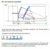
Thanks Trevor. What is "C" in the formulae?
Russ
C looks like lower shock distance from inner pin.
While we are back on suspension.
I have been reading a book ADVANCED RACE CAR SUSPENSION BY STEVE SMITH.
He talks about KPI does not need to be any more than 4deg .
The Cortina axle I measured it to be about the 7-8 deg mark.
Is there a down side to reducing KPI (mainly street some track work).
Less KPI would mean less caster & lighter steering as it only has 2.5 turns lock to lock.
Jim
oops, attempted to make them easier to understand!!
WR=(SR)(MR)(AC)
SR=WR / (MR)(AC)
Sorry
WR=(SR)(MR)(AC)
SR=WR / (MR)(AC)
Sorry
Thanks Trevor, I thought I was grappling with something new again!
Jim, if you reduced the KPI, I think you would want to reduce the caster by a similar amount. Altering the KPI will alter your camber, it's pretty much an original design decision that you are stuck with, within certain limits. Now, if you were to make your own uprights.......
All the best
Jim, if you reduced the KPI, I think you would want to reduce the caster by a similar amount. Altering the KPI will alter your camber, it's pretty much an original design decision that you are stuck with, within certain limits. Now, if you were to make your own uprights.......
All the best
Last edited:
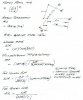
I have made a formula for wheelrate calculation that is from my Suspension book. I made a brief translation on it.
A few example of Hz numbers. My own car weights 2600p and have a 40-60% distribution. I have 3 Hz which is a Wr of 464 resp 637 p/inch. 4Hz makes Wr 726-1060P/inch.
Goran Malmberg
A few example of Hz numbers. My own car weights 2600p and have a 40-60% distribution. I have 3 Hz which is a Wr of 464 resp 637 p/inch. 4Hz makes Wr 726-1060P/inch.
Goran Malmberg
Attachments
Similar threads
- Replies
- 6
- Views
- 309
- Replies
- 2
- Views
- 666
- Replies
- 5
- Views
- 563
- Replies
- 0
- Views
- 297