8 stacks with two tanks

Seymour Snerd

Lifetime Supporter
connecting the two tanks is a problem. To connect two tanks you would have to have a common line run from the bottom of each tank to allow one tank to spill into the other as you draw fuel from one tank. I really don't have the skill level or the desire to pierce the bladder of each tank and put a cross over. I now have the ability to draw on either tank now with a carb setup the "T" with two check valves works nicely.

You can connect two tanks *and* draw from them both without an additional hole in either bladder: Connect the two existing outlets together, keep that line at the same (low) altitude, and insert a T anywhere between the two tanks that you want. Use one pump to draw from that T and supply the engine. Return to either tank or both tanks; it doesn't matter. Done. Am I missing something?

(PS: this is exaclty how the dual-tank setup on a Lotus Europa is laid out.)
 
Last edited:

Ron Scarboro

GT40s Supporter
Supporter
Lloyd,
Alan's doesn't, so you'd need to T it out so that it would drain to both tanks. It should flow somewhat evenly though it is doubtful that you would overflow a tank in that configuration. You'd need the lines to be similar in length or pressure is going to force more flow to the tank with the shorter line.

Interestingly the return line could be to a T between the T from the tanks and the pump to be recycled (Barry Grant's solution on their Sumo pumps) through the rails. The problem would be with this configuration is that there isn't sufficient volume so fuel temperature could be a problem (solved by a surge tank).

Specific to your diagram...

It should work if the pumps hold fuel between the tank and the bypass valve. If it doesn't then the pump will have to prime once started (pass air until primed) which means a loss of pressure when switching pumps/tanks. Additionally, given the way the Inglese system works that air must go out the injectors so the motor will die until the pump is primed and the air has passed. You could solve for this by installing a check valve at the tank outlet. Just NEVER run out in a tank EVER. If you do you'll have to crank the car twice 1st on one pump, then crank the car on the other pump ensuring both are primed before you drive away.

Pump priming is the main reason you have to have a swirl pot / surge tank.

Regards,


Ron
 

Seymour Snerd

Lifetime Supporter
Alan how does your method prevent from overflowing one of the tanks.

Ron and Lloyd --

Why would it? The only way a tank can overflow is if input to that tank exceeds the rate at which the cross connection can keep the two tanks at the same level. So if the cross connection is big enough it's not an issue. As I said, Lotus Europas (for one example) are plumbed exactly this way and work just fine, although they use a dead-head fuel system.

But you can pull into a gas station with both tanks nearly empty, fill up one tank, and a little while later they're both half full. So if the return line is feeding one tank, there will be flow from that tank to the other until they're both the same level. Unless of course, as I said, the cross connection is some stupidly small size (i.e. one that cannot flow fuel at a rate comparable to the return flow of the pump).

Oh by the way, another car plumbed this way is the SPF GT40: Left tank has a return port at the top and has two ports at the bottom. One port at the bottom feeds the fuel pump. Other port at the bottom connects to a long hose to a port on the bottom of the right tank. See photos below, left followed by right.

LH tank, rear..jpg

RH tank rear.jpg

So what's the problem?
 
Last edited:
Alan
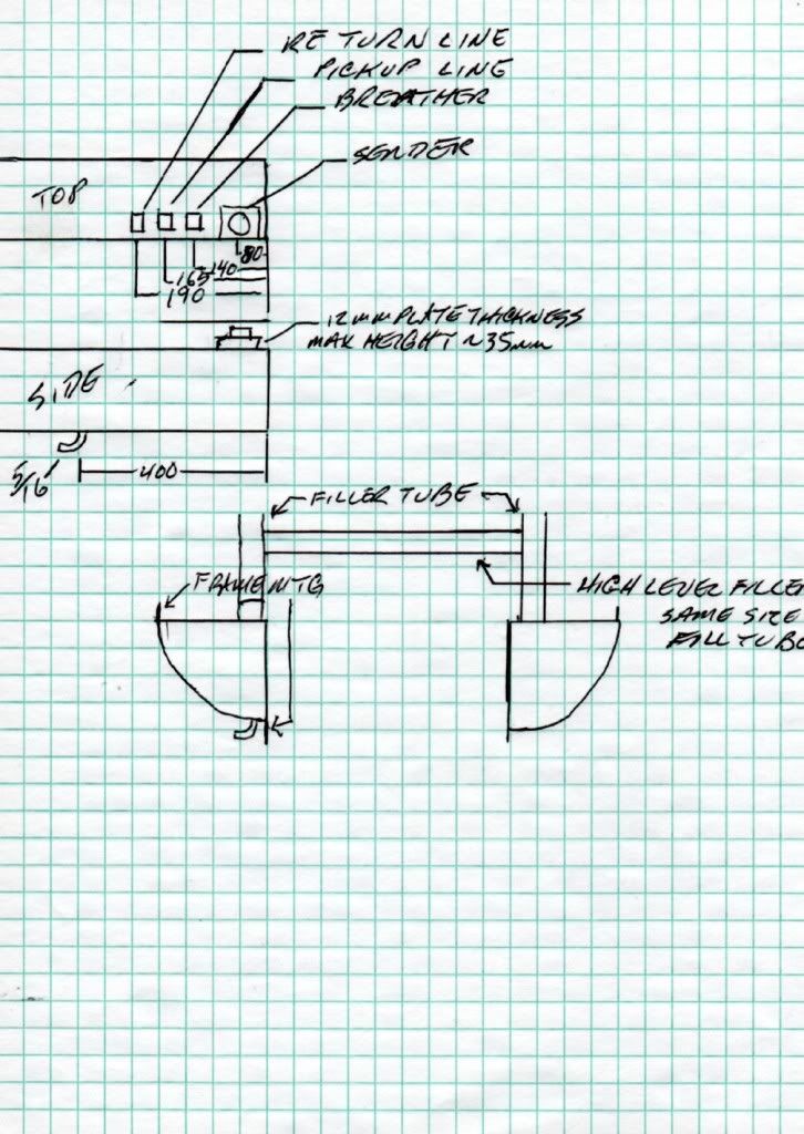
i understand the confusion now. The balance hose is at the bottom of the tank. My tanks have openings on top of the tank. The fuel pick up is center of the tank with a pickup to the bottom. Right now where the return hose goes is just a plate on the top rear of the tank. I fully understand how the tanks would equalize with a hose connecting the bottom of both tanks. my plan was just to weld an AN fitting into the plate on top of the tank for return and just let it pour into the top.

Ronald good suggestion on the check valve at the tank this would stop the gas from draining back.

attached is the drawing of my current fuel tanks
 

Attachments

  • fuellayout.gif
    fuellayout.gif
    12.7 KB · Views: 221

Ron Scarboro

GT40s Supporter
Supporter
Lloyd,
The GT40 fuel tanks are shallow and long and certainly not optimal for efi. Hard braking will starve the pump and kill the engine. On the system you propose I'd suggest putting a surge tank in eac fuel cell like the one here.

Catalog

Best,

Ron
 
Just read the entire post and I agree with Alan's idea of flow. But if you can't pull fuel from the bottom of both tanks simultaneously how about turning the tank on the driver side to a slave? You could use a smaller pump to feed the passenger side tank then run the rest of the fuel system, more appropriate pump, one regulator, one feed line, one everything else from that tank. Then the return line back to the slave tank. I'd then run the guage off the driver side "slave" tank and run the return back to it. I understand you'll always have a full tank on the passenger side but your own weight would most likely offset the imbalance in weight. Might work for your needs.
 
While not knowing the specifics of your tank arrangement, so my solution may not work for you, this was a problem that I spent a lot of time considering. I looked at various other fuel system solutions and cross over lines, etc. My solution, based on my research, is as follows.
My fuel rails have connecting pipes between them front and rear, so form a loop. Each rail has a regulator and a pressure relief valve.
Each fuel tank has a submersible pump in a swirl pot. The pump arrangement is from the big Holden Monaro V8. GTO or Vauxhall elsewhere. The pump output has built in non-return. The pump end of each fuel tank (the rear) has a baffle and a small sump built into it.
Each tank is connected to one side of the fuel ‘loop’ by high pressure supply and return lines via filters and solenoid valves that allow each side to be isolated.
This allows full system redundancy. The dash switch allows each tank / fuel supply system to be selected individually, or both to supply together, in the event you’re going to wring the big girl’s heart out and want to ensure good fuel pressure.
That’s the theory; hopefully the system will be used in anger in the next few weeks.
I agree that fuel systems don’t fail much, but I found all the separate high and low pressure systems and the tank transfer systems a bit messy. This system is very tidy, avoids all that and the redundancy is a bonus.
IMHO
 
Just an aside... does anyone know what the intermediate baffles in the RCR fuel cells look like right off? I notice there are weld marks on the outside of the tanks which would indicate a baffle plate of some sort. The welds are not continuous around the circumfrence of the tanks. Just wondering if those are mostly solid plates with some scallops along the inside edges or something like that. Thanks,
 

Seymour Snerd

Lifetime Supporter
What follows is not a solution, but it has some "interesting" properties:

Connect the tanks with a level pipe at the outlets (i.e. half way up). Draw from one of them. Return only to the top of the opposite tank.

Starting with both tanks full the pipe keeps the tanks even. Once they get below half-full, they are still kept even but now via a siphon between the two pickup points (think of the two pickups + pipe as an inverted U dipped into both tanks).

The interesting part is when one side or the other first empties enough to draw air into the inverted U. Now the siphon is broken. However, that causes the return flow to begin to fill its tank but not the other. If it fills enough to go over half-way, the siphon is re-established. If not the supply tank eventually empties completely, leaving the return tank at something below half full. So at worst you get to use 3/4 of your total fuel and then you're done.

Now, if we could figure out a way to prevent the siphon from being broken, we'd have a solution. The only way I can think of would be some kind of floating-ball valve that allows fuel to enter the siphon but not air. I don't know if those exist for practical purposes, and even if they do how they would behave under dynamic conditions (cornering, braking, ride motions). Barring that, we need a valve that automatically admits fuel but not air. :shrug:
 

Ron Scarboro

GT40s Supporter
Supporter
I may not not understand, but if you are counting on the inverted U to balance the tanks it will not. As soon as air is available that is what the pump will draw (because it is easier / less viscosity) and the pump will foul.

Putting the balance tube at the bottom (non-draw) will fix it. However, IMHO you must put some sort of surge control system in the tank if you're going to draw the high pressure pump directly from the tank due to the design.
 

Seymour Snerd

Lifetime Supporter
I may not not understand, but if you are counting on the inverted U to balance the tanks it will not. As soon as air is available that is what the pump will draw (because it is easier / less viscosity) and the pump will foul.

Putting the balance tube at the bottom (non-draw) will fix it. However, IMHO you must put some sort of surge control system in the tank if you're going to draw the high pressure pump directly from the tank due to the design.

Right. But if you can preventg the air input, or refill the inverted U, it goes back to balancing. That's where the shrug comes in.

As for putting the tube at the bottom, the origininal poster said he can't.

But anyway forget all that, because:

Actually there IS a way to fix this that actually works. Draw from the two joined output ports. Return to a T. Each side of that T has an electrically controlled valve feeding the top of its tank. Each tank has a level sensor. Whichever level sensor reads lower shuts the opposite return valve. The tanks stay balanced. Easy as pie if you can do or buy a little bit of electronics: a 50-cent single-chip comparator driving the pair of valves. There's a minor detail of having a little hysteresis in the comparator so the valves don't chatter when the levels are equal, but that's basically free in the comparator circuit.

Bingo.
 
I am using a solenoid valve on my return line. When it is resting, it returns fuel to the driver side tank. When energized, fuel goes to the passenger tank. I have both the solenoid and the passenger side fuel pump on the same power feed, so when I switch on that pump the return line is automatically shunted to the correct tank. It's not running yet, but my fingers are crossed.
 
Doug,
Interesting post answering some issues I have with a fuel injection system
install in a customer 40 build, answering your asside question----
The baffles in the RCR tanks are welded in 2-3 inch long welds on each side of the baffles, there are scallops cut out in corners to allow the fuel to flow but also to have reasonable surge control.There are 2 baffles in each tank on the RCR 40 monocoque, they are welded in very securely,I know this as here in the UK to get IVA aproval we have to fit tanks that are isolated from the cockpit/cabin via a sealed bulkhead, so the baffles have to be taken out and a tank fitted within the original RCR sill tank, as you can imagine this is a lengthy tough job working through access holes cut in to the sill front closing panel and the drilling and tapping for panels to fit back and restore the monocoques stiffness etc and also making the fill tube area isolated from the cockpit/cabin
cheers
John.
 
Originally Posted by LloydGT40 View Post
.... The fuel pick up is center of the tank with a pickup to the bottom. ...

While the fitting is in the longitudinal center of the tank, the pickup hose ends at the back end of the tank.
 

Seymour Snerd

Lifetime Supporter
I am using a solenoid valve on my return line. When it is resting, it returns fuel to the driver side tank. When energized, fuel goes to the passenger tank. I have both the solenoid and the passenger side fuel pump on the same power feed, so when I switch on that pump the return line is automatically shunted to the correct tank. It's not running yet, but my fingers are crossed.

That should work but still depends or (or offers, depending on your point of view) human intervention to make sure you don't run one tank dry before the other.

I'm still interested in no extra pumps, no extra switches, no human management.

Another couple variations of fully automoatic, single pump, dual tank idea but this time using no active electronics:

1. Find or make a very-low voltage relay eg. 1 volt; put it's coil between the output of the two level sensors. That relay then tells you which tank shouuld get the return flow; i.e if one tank is higher the relay is on, if the other is higher the relay is off. This probably renders the sensors useless for driving gauges though. But as with the electronic comparator solution they drain equally until both are empty.

2. Use sensors with low fuel light switches. Cross connect the fuel outputs so the tanks are kept even until half empty. From then whichever tank has a "near emtpy" indication gets the return flow. If they both do, one of the tanks chosen arbitrarily gets the return flow. From full he two tanks drain equally until the fuel level drops below half way. From then one of them drains to near empty while the other stays at half full. And from then the other drains to empty.

3. There's and obvious variation of #2 where you want to exhaust the tanks in order (i.e. empty the driver side first, then the passenge side). Don't cross couple the tanks, but switch the draw and return (i.e. two valves) from one to the other only when the first indicates low fuel. You need two fuel gauges to know what's going on though (or one gauge and a relay to tell it which sensor to watch).
 
Last edited:
Alan,
Why are you trying to make this so complicated.Your approach is simple enough, but you run into the problem of something electronic not working or something breaking. If you want to get the system to be simple and away from human involvement, then get away from all the electronics and go to the simple approach and let physics and gravity work for you. Dimi built a simple system which I am adapting to my car. He has had his car on the road for many months or even a year or two and has had absolutely no trouble with any of the things you guys are talking about. What he has done is to T the pickup lines and T the return lines to both tanks. There is a bottom cross over line that keeps the fuel tanks even. If that size bothers you, make it bigger. He also made it so he can fill his tanks from either side without having to wait for settling of the tanks. I don't have the room to make his crossover for the fill tubes in the front area of the car, or I would. I am still exploring that idea. I don't like the fuel lines in the drivers compartment, so I will have to deal with the settling issues for now. Here is the basic drawing of the fuel system he is using. This is for both tanks. He uses only one sender. All lines go to the bottom of the tanks with sock filters.
fueltanksetup.jpg


The only addition I have made is to baffle(trap door) the rear of the tank where the return line comes into the primary tank.
P8190255.jpg


My balance tube is outside the car underneath. the DRBs use the wash board style bottoms so it is protected.
PA270338.jpg


I am using only two pumps(one low and high pressure). That is it.

Bill
 
Back
Top