

You are using an out of date browser. It may not display this or other websites correctly.
You should upgrade or use an alternative browser.
You should upgrade or use an alternative browser.
Classic HorsePower Scratch GT40
- Thread starter Wolfman
- Start date
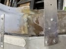
Just a quick observation with the steel making up the box sections that form the front of the chassis. They look zinc coated. ?
It may just be the lighting but if it is zinc coated please note that the fumes from the zinc when you weld are very harmful. Every effort should be made to remove the zinc from anywhere near the weld points.
It may just be the lighting but if it is zinc coated please note that the fumes from the zinc when you weld are very harmful. Every effort should be made to remove the zinc from anywhere near the weld points.
Yes sir. Good observation and reminder for those reading this or unaware. This is TIG welded and always clean any material 1/4-1” (depending on thickness & heat needed) from the welded point. Also a good reminder to always weld in a well ventilated area as well for any off gassing of impurities or unknown/unexpected potential toxins.Just a quick observation with the steel making up the box sections that form the front of the chassis. They look zinc coated. ?
It may just be the lighting but if it is zinc coated please note that the fumes from the zinc when you weld are very harmful. Every effort should be made to remove the zinc from anywhere near the weld points.
Ian Anderson
Lifetime Supporter
And do not clean anything with brake cleaner before welding
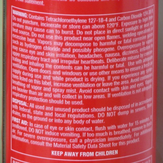
Safety Alert! Brake Cleaner = Phosgene Gas
Brew Bikes LLC 828-406-6668 Phone & Text. [email protected] BREW is a registered trademark and NO images or use without written consent.
www.brewracingframes.com
Neil
Supporter
It is OK to clean parts with Brake Cleaner before welding. What is important is to allow enough time for the solvent to evaporate COMPLETELY.And do not clean anything with brake cleaner before welding
Safety Alert! Brake Cleaner = Phosgene Gas
Brew Bikes LLC 828-406-6668 Phone & Text. [email protected] BREW is a registered trademark and NO images or use without written consent.www.brewracingframes.com
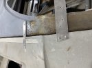
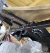
I’m calling my front support structure & clam hinge 95% complete. With the addition of the lift bar and a structural rib to the pivot brackets, I’m confident that it opens easily and can be towed or tied down from the hooks for practical use. Also appears (with some forethought) paneling this section should be easy enough and provide good channeling of air through the radiator. Next for the front section would be to deepen the twin nostrils once the radiator and fans are installed.

Found this kit that gave me some choices in lengths since I didn’t really know how it was going to turn out…it says it was for an E46 BMW. The end link bolts are smaller than the sway bar/A arm holes but this set does come with bushings to take up the size difference (with a little oversizing of the holes).
Amazon Adjustable Endlinks
Amazon Adjustable Endlinks
Been a little bit since my last update. However, it hasn’t been for a lack of working on my projects, just hasn’t been on the 40. My Cobra replica has been the priority as it’s close to being graduated to a daily driver or at least cruiser status soon as spring is just around the corner. It has a real deal 427FE side-oiler and trying to stay as close to 60’s original look as my time and budget would allow.

Will post more as it reaches final form as it still needs doors, trunk, emblems, and VIN plates mounted.
Will post more as it reaches final form as it still needs doors, trunk, emblems, and VIN plates mounted.
Mark Turner
Supporter
Looks awesome love the wood steering wheel we’re wood wheels ever used on a gt 40?
Thanks! Not sure on a GT as all the pics I’ve seen have been non-wood as I remember.Looks awesome love the wood steering wheel we’re wood wheels ever used on a gt 40?
That’s my plan…registration hoping by end of Feb or March and a few miles before the trip south!NICE
Are you bringing it to San Marcos for the Texas Cobra Club massive spring get together?
By the way, who else from here is going to the Texas Spring Cobra Meet?? I’ve seen a GT40 or two in attendance over the years and hope to meet some of you there and in person.NICE
Are you bringing it to San Marcos for the Texas Cobra Club massive spring get together?
Finally committed to fusing of the rear spider sides to the roof panel. Started with final shaping of the filets and a couple screws to hold things in place at the proper angles and such. Then I mixed Silica powder to thicken the epoxy resin into a ziplock bag to make it easier to apply as a bonding paste. Once dried, I removed the single unit and reinforced the underside with some more of this paste as well as a couple layers of new fiberglass. After reinstalling the unit onto the chassis, I ground the joint to a more accurate shape on the exterior/exposed surface to add more bonding agent and fiberglass layers for its semi-final shape.

Attachments
Got some time to start the bonding of the roof skin (and now spider uprights) to my spider endoskeleton. Had to bolt everything down in the back of the spider to make sure nothing had changed and trial fit the windshield again. My type A perfectionist wasn’t happy with the fit, so more cutting, grinding and welding was required x2. One final roughing up of the bonding surfaces and made an icing (ziplock) bag of thickened epoxy onto the metal skeleton and laid things in place.
The plan next is to remove the now bonded outer structure and turn upside down to reinforce further with fiberglass mat, epoxy and a little more bond icing to dry before bonding the inner upper roof panel. Will also do some reinforcement bonding to the windshield base while it is upside down. What looked like a sack of unusable fiberglass parts is actually starting to take form.
This part of my build was my most feared, stressed and doubt filled task to overcome (in my mind at least). This was mainly due to the unknown measurements, poor skin molds, and missing A pillars that all had to be overcome. A HUGE THANK YOU to all those that contribute to this forum for your unknown help of pics, measurements, and encouraging build experiences that I have been able to get the confidence and knowledge to be able to do this!
Last edited:
Like the approach you've taken using both square/rectangular tubing combined with bonded inner and outer roof section surface skins. Think this will add some overall torsional rigidity to the chassis (compared to fiberglass-only spider) without introducing the protrusion of larger diameter roll cage tubes within the passenger area and potential safety issues as discussed in previous threads. A win-win in my books. Was just wondering about how the rear bracket of the central tubes is attached to the rear hoop. I assume something like a welded/bolted L-bracket?
Yes, it’s an L bracket with square tubing and am securing with a couple of bolts going up through the top bulkhead. I am also planning to fill the air void between the two skins with expanding foam to add some more structural strength, sound and thermal insulation value with the extreme Texas heat we get.Like the approach you've taken using both square/rectangular tubing combined with bonded inner and outer roof section surface skins. Think this will add some overall torsional rigidity to the chassis (compared to fiberglass-only spider) without introducing the protrusion of larger diameter roll cage tubes within the passenger area and potential safety issues as discussed in previous threads. A win-win in my books. Was just wondering about how the rear bracket of the central tubes is attached to the rear hoop. I assume something like a welded/bolted L-bracket?
Attachments
Similar threads
- Replies
- 65
- Views
- 8K
- Replies
- 9
- Views
- 2K
- Replies
- 16
- Views
- 2K