Exhaust Modeling Kits

PaulProe

Supporter
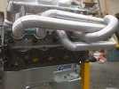
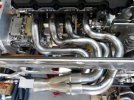
I have a question for the brain trust - those who have or are using the Icengineworks modeling kit (or clone version) to generate their bundle of snakes exhaust.

The Icengineworks kit is designed so that each adapter has a 1" centerline length with the idea you can match your exhaust tube length very easily. Good in theory but I can see an issue in routing the tubes. Example: using a 4" radius adapter, a 1" centerline length calculates to 14.32 degrees. You can not generate a 90degree bend with the adapters, it is 86 or 100 degrees.

The fit under the body and clearing the necessary pieces can get very complicated and I can see issues if you can't run the pipes on basic angles. ie, the pipe for number 5 runs parallel to the cl of the engine, so to feed it from the #5 exhaust port, you need a 90 degree bend. Using 86 or 100 creates either joint gap issues or a pipe route that is not where you want it to go.

I am probably overthinking this, but curious what others have done. I am working on a clone system and can model the adapters in either 1" CL length or 22-1/2 degree faces. Looking for someone who has used the kit to comment on how they got around the lack of being able to do square corners or how precise their tube joints were before welding. I know for tig welding thin wall, you want as good a joint as possible - an 1/8" gap is just going to be a problem. Likewise, not being able to run the tubes parallel to one another creates another issue.

Thoughts?

Thanks

Paul
 
I made mine like you did 22.5 degree increments, I know what the centreline lengths are for each part so you just sum them up when you're done and tweak your straight sections as needed.
For TIG I but up tight, no gap anywhere, mig I don't care so much an 1/8" gap is nothing if it needs to be like that to cheat things.
 
I modeled and 3D printed a bunch of segments in radii Stainless Bros carried.

I have 22.5 deg, 30 deg, 45 deg in both radii and straight cut to length piece that fit together with a friction fit.

So far I've only played with my legos because I'm waiting on a transaxle

Best part, it only cost 30 bucks worth of filament and some otherwise needed cad practice.
 

Attachments

  • header mock up1.jpg
    header mock up1.jpg
    295.8 KB · Views: 94
  • IMG_20221012_124800.jpg
    IMG_20221012_124800.jpg
    388.8 KB · Views: 95

Pete

Lifetime Supporter
I did use the ICE ENGINE system. In the end I needed to make extensions for the longer tube sections. I mocked up what I thought would be good. I was basically fitting up for clearance to the body. There is a picture in my build thread of the finished pipes. It was helpful but I think the price was a little hefty. I have pictures of it in use if you'd like.
 
It's not a bundle of snakes header but probably even more complicated layout. I decided the plastic mockup approach wasn't going to tell me everything I needed to know, so I built a "prototype" using cheap steel mandrel bends prior to building the actual header in 304 SS. Probably takes more time than the plastic mockup approach but it worked well for me. With 304SS, you want to weld joints to be absolutely tight for welding if you don't want to have big lumps on the inside. The tighter the fit up, the less intrusion you'll have on the inside of the weld joint.

The other factor was my header design called for an increasing tube diameter through the header primary tubes so I would have needed 3 different sizes of mockup units. The primary tubes started at 1 5/8", went to 1 3/4" and then up to 1 7/8" before reaching the collector. The header experts say the increasing primary tube size makes a difference so I went that way even though it complicated the routing mockup process.
 

Attachments

  • P1160362 - web.jpg
    P1160362 - web.jpg
    74.7 KB · Views: 61

Scott

Lifetime Supporter
I used icengineworks to design a complex equal-length 180-degree crossover exhaust (it actually crosses under the dry sump) The primaries step from 1-7/8" (green) to 2" (yellow) so I used multiple kits. The merge collectors fire in a proper rotary sequence, one side is CW and the other is CCW. Like you I was worried about being able to make a perfect 90-degree, so I designed and 3D printed a custom block for each CLR. that would create a perfect 90 degree. I even set up a spreadsheet to calculate the distance for each block (keep in mind that I had two diameters, so it was twice the work). Guess what? I never used them!

1705980649186.jpeg


I learned a couple of things:

(1) I found it very hard to visualize what I was trying to do adding one block at a time. Things got much easier when I pre-made U-bends held them in place and then decided where to snap them apart. And then at that point I might add or delete blocks incrementally.

(2) Mark the CLR in sharpie because it really sucks when you figure out that somehow a different CLR snuck into your perfect arrangement. The cast labels are legible, but they're small and some times they might be facing the block.

(3) I highly recommend their tacking brackets. While they don't work if the joint is far into at tight CLR, they are a God-send for many joints. They make it easy to incrementally replace a plastic section with a metal one, clamp it up to guarantee everything is clocked correctly and then tack it and move to the next.

(4) To handle the diameter changes I disassembled several tacking clamps and then reassembled them to utilize both diameters in the same clamp. It worked like a charm. However, carefully mark these ones because at some point you'll wonder WTF won't the tube fit and it might take you a while to determine that the other side is a smaller diameter.

While there were lots of scraps there wasn't one piece of metal that was cut and tossed because it didn't fit. I can't comment on any of the other kits but icengineworks worked great. Whatever you choose, make sure that they stay together. It really sucks when pop apart and you need to start all over.

1705981740467.png

1705981788541.jpeg
1705981832861.png


1705981911114.png
 

PaulProe

Supporter
Thanks for your responses, guys. A second question

As you started your build, did you try to use the same bend radius everywhere, or did you find yourself mixing pieces to get the layout you want? I can see it would be easier to use the same bend over and over but can also see there may be a place a different radius would work better

? ? ?
 
Haven't built anything yet, but from a little playing around I can say you'll want at least 2 or more likely 3 different radii or you'll have the longer sweeps looking like truncated squares.

The back couple of cylinders usually make a long sweep around up and over. Without long radius bend there, imagine what it'll look like.
 
In my case, I probably used every bend radius available. It would be nice to use all the same radius but that's probably only possible with very simple header layouts. I tried to stay away from tight radius bends due to flow restrictions but there was a couple of places I had to use them. My approach was to use the largest radius bends where possible and work down to the tighter radius bends as necessary.
 
Back
Top