Failed Shock Mount

Seymour Snerd

Lifetime Supporter
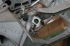
One difference I think I see between mine 2160 and Jim's 2264 is that along the line where Jim's broke, mine has tack welds/brazes top and bottom, and I don't see those, or evidence of them, on Jim's (where the red arrows are below).

Jim shock mount annotated.jpg

Without those, that side piece that broke goes a long way inward, toward the center of the car, before it's attached to anything.

It's a very difficult area to visualize because over most of its area it's two layers thick, but the two layers aren't connected to each other in very many places. But th the U-shaped shell in which the shock upper mount is bolted is just one layer of 22-gauge steel, and on it's own would be quite flexible. Only the sides of the U are connected; the "top" of the U is just a bridge.

That's why I think it depends on the bolt and the shock eye for rigidity. And even with that the anti-roll bar might be flexing it a lot. One thing I'm tempted to do with mine is simply close the bottom of the U so it's a box. And maybe connect the top of the U to what's behind it.

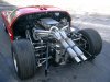
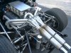
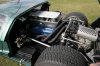
Sure wish I had a "real" one to look at....

I wonder if one of our Mirage-owning friends, or Andrew K, would take some pictures for us...
 
Last edited:

Jim Craik

Lifetime Supporter
Steve,

I looked at your photos, it appears that you moved the sway bar mount to a separate plate. Was this to remove any potential twist to the mount?

Additionally, does that new plate add reinforcing to the shock mount or just give a place to mount the sway bar?
 

Seymour Snerd

Lifetime Supporter
Jim -- this is perhaps over-examining your picture, but when I look at the broken edge it looks distinctly dirtier at the bottom than at the top, as if it were a crack that grew upward. Perhaps you can tell if that's really true and not a photoghraphic artifact of some kind.

And of course per my speculation above it would be interesting to know if on the inside of the broken off piece there are the remnants of welds/brazes at the top and the bottom.
 

Steve C

Steve
GT40s Supporter
Jim,

You asked:
"I looked at your photos, it appears that you moved the sway bar mount to a separate plate. Was this to remove any potential twist to the mount?
Additionally, does that new plate add reinforcing to the shock mount. "

Yes to both of your questions.

Steve
 

Seymour Snerd

Lifetime Supporter
Here's how Mk II P1032 did it:

rear anti-roll bar mount.jpg

Those guys didn't screw around....

Notice the thickness and the shortness of the the shock mount ears... maybe the earlier Mk I design added just a little too much lightness...
 

Jim Craik

Lifetime Supporter
Steve,

The more I look at all this, the more I think that you have called the problem.

Although the stock sway bar mount is simple and light, I think it adds an un-needed twisting motion to an area that is fairly light construction.

It may be that my fairly high mileage has allowed this minor twisting motion to slowly fail this somewhat thin piece of steel.
 
Last edited:

Jim Craik

Lifetime Supporter
Alan,

P1032 appears vastly different, was this a one-off mod or were the early racers constructed differently?
 

Seymour Snerd

Lifetime Supporter
Alan,

P1032 appears vastly different, was this a one-off mod or were the early racers constructed differently?

All the Mk II's that I've been able to find show that kind of anti-roll bar mount. I haven't found a clear photo of an original Mk I mount (yet).

Here's the relevant page of the parts book. The frame construction appears the same as ours (to the extent that the level of detail allows), however, the antiroll-bar is mounted with its centerline directly above the shock and in a rigid structure that probably helps stiffen the shock mount, so there is much less twisting moment about the mounting ears. There is still some from whatever friction there is in the bushings, but nothing like on our cars.
panel_t.jpg

panel_a.jpg

By the way, please note that one solution to this problem is simply to remove the anti-roll bar, like on this Mk II. You'll have more understeer, but is that necessarily a bad thing?
gt40-427-1-1.jpg
 
Last edited:

Jim Craik

Lifetime Supporter
Guys,

Thanks for all your help, truly great info! Now I'm thinking about a fix. I'm thinking a tack weld to hold the shape then a triangle piece of steel attached to the three conveniently placed bolts. I'm thinking four plates one on each side of the shock mount, and of course both left and righ side.
 
Last edited:

Seymour Snerd

Lifetime Supporter
Guys,

Thanks for all your help, great info! Now I'm thinking about a fix. I'm thinking a tack weld to hold the shape then a triangle piece of steel attached to the three conveniently placed bolts. I'm thinking four plates one on each side of the shock mount, and of course both left and righ side.

That should work, although my first impulse was to in some ways replicate the piece that broke, IOW rather than two triangles on each side, make one U-shaped piece the sides of which are shaped like your triangle pieces. And then weld it all the way around its edges. But that's more work and your version will probably work fine.

BTW I believe that, aside from the spot welding, the "welding" was in fact brazing.
 

Jim Craik

Lifetime Supporter
Alan

I'm sure that a U shaped brace would great, but bending a somewhat thick piece of steel is beyond my skill set. By the way how thick a piece of steel should I use?

I'm not all that sharp when it comes to steel. How does brazing differ from "welding". Also, is the GT40 tub brazed, welded or maybe both?
 
Last edited:

Jim Craik

Lifetime Supporter
Brian

That's a great looking solution, I know many of the original 40's had serpentine sway bars, will yours go over or under the exaust?

That sway bar has some intricate machining, where do you get something like that?
 
This sway bar was fabbed from 5/8 cold rolled. The shock tower mounts were imaged from original. All one off from cutting, welding, bending and machining in the shop.
 

Attachments

  • P1010349.jpg
    P1010349.jpg
    201.4 KB · Views: 368
  • P1010351.jpg
    P1010351.jpg
    203.2 KB · Views: 337

Brian Stewart
Supporter
That is Classic Car Developments (Dave Brown) handiwork Jim. The bar goes over the exhausts. Here is a similar bar on one of Dave's finished cars.
 

Attachments

  • LJs car.jpg
    LJs car.jpg
    159.5 KB · Views: 386

Dave Bilyk

Dave Bilyk
Supporter
Jim, I don't disagree with anything said here, strengthening would be a good step. But regarding causal factors, I see some signs of corrosion, but not well enough to be sure. Is it possible that corrosion has allowed a crack to initiate? These thin sections aren't very corrosion tolerant, so it can't take much to set off a crack.

I always wonder when I see these thin sections used for mountings, on my car (DAX) the trailing arm - chassis mounts are the thinnest metal on the whole car.

Dave
 
Back
Top