Front Suspension Geometry

I have been moving through the front suspension on my RF.
I have to say it has been the most time consuming projects on the car so far.

I have made another set of arms with ball joints to give travel and all is going well.
The reason for this post is to share a technique that was on a earlier post about bump steer testing with a laser pointer.

I gave it a go this morning and I have to say it is much easier than dial gauges.
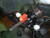
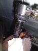
I set the laser on the hub and shot it 90 deg off the centre line of the car.

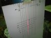
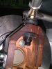
I put some lines on a cardboard sheet as a guide, I taped it to a gas bottle and went through the motions.

It took hardly anytime at all to work it out because it is black or white.
With the dial gauge method as the wheel travels up you have to subtract the camber gain and I find I have to keep checking the direction they are rotating as to whether it is toeing in or out (or maybe its just me).

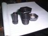
I kept shimming the arm and could see the changes with a 1.6mm washer thickness.
It took about 15min and I checked it after with the dial gauge and it had .006" toe in over a 3" range 1 down 2 up above and below it is still respectible.
I am resigned the rack is to long in the body (thats life).
I thought I may get it closer with the dials but that was not the case it was as good as it was going to get.

I thought I would share the results as it is effective and cheap and to be honest way easier to do.

The card has toe in and out a centre line and some height datums.
I set these by moving up 25mm at a time and making a mark on the card.
My laser shoots a line so I put tape over the front a poke a pin hole in it to make it easier to read.
I took the tape off for photo purposes.

Jim
 

Attachments

  • bump steer 1.jpg
    bump steer 1.jpg
    56.2 KB · Views: 770
  • bump steer 3.jpg
    bump steer 3.jpg
    41.5 KB · Views: 753
Jim
Very interesting setup ..I have used this because of the limitations of the dial indicators that you mentioned. Also if I may add a few things I have found.
From the photos I can't tell whether you have any anti-dive built into the front end..this will add some caster in bump and possibly some steer input but minimal.
I originally had upper wishbones setup with a ball joint at the upright and rod ends at the chassis and found that setting up caster/camber was difficult as one affects the other when the rod ends are extended/shortened..I am now using a mono bolt at the upright and bushings at the chassis which I shift fore and aft with shims to adjust caster...almost no effect on camber this way..but takes a little more time to adjust, and camber is done right at the outer rod end.
Also...I wouldn't worry too much about running a lot of camber gain on a chassis with minimal body roll, although you may be limited in wishbone length due to footwell space considerations, and your upper arm being much shorter will introduce it. Lengthening the instantaneous center by moving the upper inner mounts up will help, but check as you go...maybe 140 to 150" at ride height would work as a guess.
It seems you have a good handle on the whole thing, and if you have the time (and patience) trying different setups will tell the tale.
I can tell you that if I have bump steer that is difficult to remove I always try to set it to get toe in at full or almost full droop if I can't eliminate it and try for none thru the rest of the travel.
You mentioned that you had a steer rack that was too long..a simple trim on one end where the inner tie rod end screws on...maybe a little shorter than you need, then you can shim it out as needed, only problem it will shorten the rack travel a bit, and you may want to re-center your steering but these are easily accomplished.
Hope some of this helps
Cheers
Phil
 
Thanks Phil it does help.
People who have been there before to point out detail is good.

You are correct about the caster change with camber adjustment I noticed that this morning when I went one extreme to the other on neg camber to see how much I could get.
Moving my instant centre has given about another 1/2 to 3/4 neg with my measureing that may not be super accurate (spirit levels ect).

Yes it does get some caster gain but I dont think you can stop that .

The front pick up on the upper arm has anti dive( it just turned out that way) but Im not going to use it.

Funny thing with moving the instant centre I have noticed it can take a lot and not lose camber control in bump or droop.

This is a genuine question for anyone who can give a different angle on it.
I have conflicting storys on Roll centres but my general view is you have your C of G and you have your roll centre lets say under the car at say 50mm off the road.
You then have a distance of say 200mm between the roll centre and the CG this wait mass above the RC will have to be controled by the springs and s/bars.
If you raise the RC and still keep everything else under control ,camber control ,Dynamic roll centre ECT ECT and keeping in mind that you want front to rear roll centres similar distances from CG to keep the car balanced is this
In doing this will it not reduce the mass above the RC inturn requiring less spring rate and less sway bar.
I hope my explanation is clear enough to get some feed back.

At this point my game plan is to do some road rally events if I ever finish this thing and the road conditions are not always the best so to allow the suspension to work a little more may help keep it on the road.

Jim
 

Russ Noble

GT40s Supporter
Lifetime Supporter
Jim, if you raise your rollcentres by definition you also raise your instant centres. Too much can lead to a jacking effect, also if you have achieved the higher RC through raising your top link inner pivot and you wish to run softish (relative term!) springs for road/rally, you may not have enough camber compensation for the long suspension movement in roll and you may get excessive negative on your inside wheel as well as too much positive on the outside. Nothing's free, it's all a compromise. Heavy bars plus the higher roll centre will help, but.....

IMHO. Now let's wait for the experts!

Cheers
 
Phil I am not familiar with the term mono bolt (is it a single bolt through a rose joint into the upright).

Russ
This is good info it helps get our head around things you dont realise you are inducing.
So the higher RC causes the car to rise like on a pan hard rod effect.

Yes it is a relative term(spring rates) Like Frank Catt stated earlier every car is different and has different needs.

The RF had a large bump steer issue in the rear I do feel that the owners out there fitting higher spring rates are seeing gains in the handling department because it is controlling the amount of suspension movement and the amount of bump steer in the rear which does make sense and I am not having a stab when I say that.
I have rectified all that so I am thinking I can run with the 250 -350 rates there about
As it will behave.

I think some of it will come down to suck it and see to find the limits of some of the settings roll centres ect.

Put some pics of how I am adjusting the roll centre.
I made it out of a 1" unf bolt
You shim up under the head of the bolt between the upright.
A taper is machined into the bolt for the ball joint.

Sorry to bug you guys but know you love it so its ok I guess.

Jim
 

Attachments

  • Copy of roll centre adjuster.jpg
    Copy of roll centre adjuster.jpg
    46.9 KB · Views: 691
  • Copy of roll centre adj 2.jpg
    Copy of roll centre adj 2.jpg
    26.2 KB · Views: 691
  • Copy of roll centre adj 3.jpg
    Copy of roll centre adj 3.jpg
    52.2 KB · Views: 716
Last edited:

Russ Noble

GT40s Supporter
Lifetime Supporter
So the higher RC causes the car to rise like on a pan hard rod effect.

Sorry to bug you guys but know you love it so its ok I guess.

Jim

Similar Jim, but there aren't really any serious handling issues with properly mounted Panhard rods. For an extreme case of suspension jacking, think old VW Beetle rear (short SAL, high RC) . Camber compensation is a good effect in a chassis with a reasonable range of suspension movement. Phil suggests an effective SAL of 3.75, I prefer about half that. I'm using 1.5 on my build.

Talking about bugs, when did you last borerbomb your upright?!!:lol:

All the best,
 
Last edited:

Chris Duncan

Supporter
IMHO,

the upright should be a little less deep and the arms longer. You're going to have a lot of scrub radius with that set-up.

Agree with Frank Catt, design from the tire inwards.
 
Last edited by a moderator:
I do appreciate the input it is giving me a better feel for the way I want to go with this.

Kalum yes I agree the top arm should be longer I tried this length to keep the camber gain that was already there but I am over that.

Everything said I have taken onboard.
I will start from the wheel in (Thanks Frank).

My original idea was to run with about 4 deg KPI the mock upright has 6.5.
The original stub has 7.5.
This is why I made it in wood as I didn’t want to set anything in concrete at this point.

The upright does look deep because the modular bearing is about half the depth of the original wheel hub so the space is taken up with upright, a flatter disk would be ideal.

I will go away and play with this I will post when I am happy.

Jim
 

Malcolm

Supporter
Having just got back from holiday I have stumbled onto this thread. Quite interesting having just gone through similar exercises myself for replacng my front uprights. Hopefully the new ones will be with me within three weeks time for fitment.

Some comments on KPI I picked up in my discussions prior to placing my order.

1. The general range of KPI is between 4 to 7 degrees.
2. Conceptually the aim is to get the line to intersect with the ground in the centre of the tyre, however a test was done a couple of years back with I think it was a Renault Laguna when they ran different KPI from the centre of the tyre to 2 inches beyond the inner tyre wall ie towards the centre of the car. There was no difference in lap times.
3. If you run a high KPI combined with a higher castor angle when you turn the wheel in a corner surely it will lean like a motorbike wheel? Citroen 2CV?
4. Isn't the purpose of KPI to counter the cars lean during a corner, ie keep the tyre footprint flat on the ground? GTD40's tend to not roll that much (especially track versions) so potentially is not a high angle as concerning as a very low angle?

All things lead to a compromise and you just have to choose the best to suit your intended use of the car. A stiffly set car will potentially hide problems that a softer car will show up. I am in the process of softening my car back to a predominantly road set up.

If a back to back test is of interest then I have just ordered a set of front uprights from the same supplier where Frank gets his from but I have had 5 degrees of KPI put into mine. I am having a custom steering arm made in the same vein as Frank's but not as radical, to improve the Ackerman situation over a standard GTD. I had this on my previous uprights but felt that as the car is more likely to be turning at speed than in a car park down the local shops I would rather have the higher speed end of the range covered than the low speed end.

A different viewpoint perhaps but hopefully it all adds to the melting pot of information for consideration.
 
I have also been trying to learn more about this subject, a good place i have found to ask these questions is here, you have to register etc but these guys really know what they are about, most of them are design engineers and so do it for a living, here is a post about KPI and trail etc on a mcpherson setup but if you search the site , there is heaps of answers to this and other curly suspention questions.
Automotive suspension engineering - Kingpin Inclination, Caster, etc. for McPherson strut

hope this helps
Best Regards
Lambo
 
Malcolm , I assume that the Laguna would have been front wheel drive and have the luxury of power steer. In the case of the GT40 or for that matter any RWD car a setup as you described on the Laguna would have a large scrub radius and probably result in tyres fouling the wheel arch on full lock, also if the tyres hit a kerb or had contact with another car it would probably have enough leverage that the driver would not be able to hold the steering wheel and maintain control.

Jac Mac
 

Russ Noble

GT40s Supporter
Lifetime Supporter
Having just got back from holiday I have stumbled onto this thread. Quite interesting having just gone through similar exercises myself for replacng my front uprights. Hopefully the new ones will be with me within three weeks time for fitment.

Some comments on KPI I picked up in my discussions prior to placing my order.

1. The general range of KPI is between 4 to 7 degrees. Malcolm, basically true.
2. Conceptually the aim is to get the line to intersect with the ground in the centre of the tyre, however a test was done a couple of years back with I think it was a Renault Laguna when they ran different KPI from the centre of the tyre to 2 inches beyond the inner tyre wall ie towards the centre of the car. There was no difference in lap times. ie changed the scrub radius. I don't think it affects road holding, only steering kickback on bumpy surfaces.
3. If you run a high KPI combined with a higher castor angle when you turn the wheel in a corner surely it will lean like a motorbike wheel? Citroen 2CV?No, I don't think so, you need the high castor to compensate for the high KPI so you can keep the wheel upright.
4. Isn't the purpose of KPI to counter the cars lean during a corner, ie keep the tyre footprint flat on the ground? GTD40's tend to not roll that much (especially track versions) so potentially is not a high angle as concerning as a very low angle? Hmmm, I'm not so sure. I thought it was to counteract castor which you need to give the steering a self centering effect. KPI was around in the days of beam axles, obviously body roll had no effect on wheel angles in that case.

All things lead to a compromise and you just have to choose the best to suit your intended use of the car. A stiffly set car will potentially hide problems that a softer car will show up. I am in the process of softening my car back to a predominantly road set up.

If a back to back test is of interest then I have just ordered a set of front uprights from the same supplier where Frank gets his from but I have had 5 degrees of KPI put into mine. I am having a custom steering arm made in the same vein as Frank's but not as radical, to improve the Ackerman situation over a standard GTD. I had this on my previous uprights but felt that as the car is more likely to be turning at speed than in a car park down the local shops I would rather have the higher speed end of the range covered than the low speed end. Malcolm, I'm not familiar with the nuances of GTD Ackerman are you saying you are going from partial Ackerman to full Ackerman, or vice versa?

A different viewpoint perhaps but hopefully it all adds to the melting pot of information for consideration.

A good contribution Malcolm, might spark some more discussion. Edit. Already has! Whilst I was typing (slowly!!) and thinking (even more slowly!!) a couple of other replies have come in! I always find every time I participate in these technical threads I learn something new.

Cheers
 
Last edited:

Malcolm

Supporter
Hi Russ

Jumping to your comment on my point 3. I looked up the castor angle on the 2CV and it is 15 degrees! However I suspect it has a fairly normal KPI as the tyres are so narrow, like a motorbike! I couldn't find its KPI angle. I beleive Frank likes the cars that he works on to run high castor angles. I think it is somewhere in the region of 7 degrees of castor but I am happy to be corrected. Please note that I work on third hand information on Frank's set ups as funnily enough he doesn't post me his set up sheets! The standard GTD set up is something like 3.5 degrees. The standard GTD ackerman is poor. In fact it could well be negative ackerman which sounds, and is daft. I got rid of this with my previous set of uprights and ran very slightly positive ackerman. Made the steering very light indeed so I increased castor to about 5 degrees just to get a steering weight I was happy with. When I get my new uprights I intend to start with standard castor and then adjust to suit what I fancy at the time. I am also going back towards zero ackerman, still a better situation than the standard GTD set up! Maybe I am not yet fully ready to let go of a track set up on my car after all!

Hi Jac Mac

The Laguna is a front wheel drive car. I am not aware of standard GTDs fouling their bodywork, certainly mine didn't when it was standard. I am not sure anyone should be designing their suspension to deal with hitting kerbs or other cars as a standard feature other than to make it strong enough to not collapse in said scenario! Certainly this can't be described as a typical road car concern? Maybe you drive differently in NZ!
 

Russ Noble

GT40s Supporter
Lifetime Supporter
Hi Russ

The standard GTD ackerman is poor. In fact it could well be negative ackerman which sounds, and is daft. Maybe I am not yet fully ready to let go of a track set up on my car after all!

Hi Jac Mac

I am not sure anyone should be designing their suspension to deal with hitting kerbs or other cars as a standard feature other than to make it strong enough to not collapse in said scenario! Certainly this can't be described as a typical road car concern? Maybe you drive differently in NZ!

Malcolm, anti Ackerman is common on a lot of race setups, the logic for it is that under race cornering the outside wheel is heavily loaded and consequently the tyre is running at a much greater slip angle. Anti Ackerman compensates for this by turning the outside wheel tighter than the inside. You can look around the single seater pits and see fast cars with both setups, so I think it's like scrub radius, really has no significant effect on track times. FWIW I am going with full Ackerman on my build, but only so Jac Mac will find the car easier to push around the pits.:pepper:

You're right about not designing for hitting kerbs. But I take it that Jac Macs reputation and escapades haven't made it as far as the UK! Yet! His experiences may put a different perspective on his suspension design!:lol:

Cheers,
 
Malcolm,

I was not suggesting that the GTD or any current GT40 car would have problems fouling guards etc, but if you were to adopt a setup similar to the Laguna with large scrub radius it could become a problem. Interesting to observe that the 'new' Ford GT appears to have front wheels with considerable rear offset.

Russ is such a mechanical perfectionist that I am sure he will have the forethought to fabricate a couple of sets of wheel dollies ( Non-skirted variety) one set of which will be fitted with All Terrain tyres, powered by reject GO-Ped powerplants so that he alone can manouver his car easily in the pits.

One innovation that I have been looking at incorporating in my own cars is the double lower ball joint 'virtual center' setup to help decrease scrub radius and not have suspension interfere with rotor dia etc.

Jac Mac
 
Jim
Mono bolt is what you might call a combination of a spherical bearing and a tapered bolt to go through the upright. Generally you can accomplish this with a rod end and a tapered bolt, but most rod ends don't have enough travel to keep them from binding in full travel. The mono bolts use a larger spherical bearing mounted in a sleeve which can be welded into the wishbone, or have a threaded end depending on how you are acheiving camber adjustment. The advantage is the bolt can be shimmed up or down in the bearing to change intantaneous center and therefore roll center slightly..the disadvantage is the open bearing which attracts dirt etc.. I can post a photo if you are interested.
Cheers
Phil
 
Yes Phil I am interested in a pic thanks.
The lack of travel was an issue I had with spericals but the general size of them has its advantages.

Malcolm

How is it the steering in your car got considerably lighter with an ackerman change.
My thought is the tyres are not working against each other, but I would not expect much difference at speed but it sounds like that is not the case.

Thanks for the link Lambo more people I can annoy.

Jim
 
Jim, Trying to get a photo of the mono bolt, but all I could get was this crummy photo, I will get some actual photos next week of the real thing.
Cheers
Phil
 

Attachments

  • 58086-EX2892.jpg
    58086-EX2892.jpg
    6.1 KB · Views: 556
Back
Top