Front Sway Bar Brackets

Bob hit on some very good items (which I also questioned, but didn’t comment due to the fact that many times a photo misrepresents what is actually there).

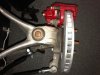
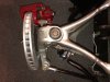
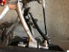
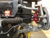
His first point was that if you draw a centerline from the mounts and extend that out to the wheel, the distance of that centerline, to the mounting point on the lower control arm (as viewed from a vertical, above the chassis perspective, with suspension in the loaded position), you should have an effective arm length that promotes a twisting action on the bar, rather than a vertical bending motion on the bar. The shorter this arm length, the less twisting force is applied (desired), and the more bending force is applied (not desired). In an extreme example, the arm length is zero, and thus no twist takes place at all. BTW, has this bar been bent or changed any way from the OEM use? The reason I ask is that if Bob’s point here is valid, it would mean the OEM application was flawed to begin with, which I highly doubt unless the bar has been flatten somehow. If the bar is un-modified, than moving it further forward from the arm does no good because you'd lose any advantage by introducing angles into the bar's links.

His second point is completely independent of the first one, and that is the distance of the mounts (and this is assuming you have a viable arm length). Look at this from an exaggerated perspective of having both mounts within an inch of each other. In that case, regardless of the bushings used, you’d have a force that would try to rotate the bar at a point centered between the mounts (in essence, the system sees this as a single mount rather than two of them), with no twisting motion provided as desired. As the mounts are moved outward from that exaggerated position, there is a shift from the rotation force to a twisting force on the arms, until you reach the ideal position where both mounts are a distance from each other that equals the distance of the control arm attachment points from each other (again, this is ideal but not practical). Yours are somewhere in the middle of these two extremes.

His third point is that rubber mounts compound all the problems noted above.

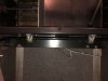
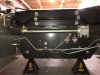
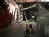
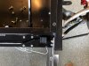
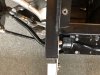
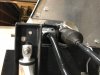
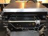
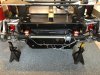
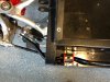
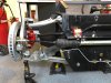
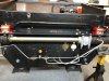
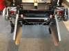
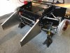
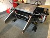
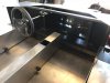
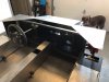
Based on your original posting photos, could you not locate the mounts on the horizontal surface immediately under the current vertical plate?. This would allow them to be moved further out laterally (out to the welded vertical brace), where it appears the original OEM mounts may have been located?

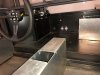
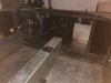
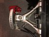
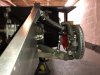
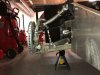
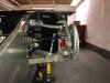
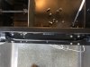
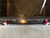
What would also help folks here is to get some photos from directly above the assembly, with the assembly position as it would be on the road, as will as directly in front of it, and directly to the side of it (the three planes parallel to the ground, perpendicular, and laterally). The angles of the posted photos, of an unload suspension, make it hard to see if there really is a problem (or degree of problem) here.

Thanks Terry. I now understand a little better and also understand why the current configuration isn’t desirable.

It is not a bent or custom bar. It also came from a C5 Corvette however it’s a rear bar. The front Corvette bar is way too large.

I’ll do my best to take some pictures of the angles you suggest, however there still won’t be a load on the suspension.

I’m still not sure wher I should install the bar, so if after I post the pictures, maybe you could write back and make recommendations.

Thanks again Terry
 
Here are some footwell pictures. For some reason Chris has a battery box in the footwell. I’ll probably remove that and reposition the battery somewhere else giving me more foot room.
 

Attachments

  • 7CE066F5-F392-4BFD-9E75-77175549BC18.jpeg
    7CE066F5-F392-4BFD-9E75-77175549BC18.jpeg
    79.9 KB · Views: 234
  • 23CD9BE8-0AA6-4D64-8D7C-95895BE8F08C.jpeg
    23CD9BE8-0AA6-4D64-8D7C-95895BE8F08C.jpeg
    62 KB · Views: 200
Terry here are the pictures you asked me to take. If there is an angle I missed, just let me know and I’ll take some more.

I just want to get the bar mounted properly. Any suggestion as to specifically where, I’d really appreciate it.

Steve
 
I’m having trouble loading them so they’re not in any sort of order.
 

Attachments

  • 695C8743-38A3-4002-8C9A-F29D47466A76.jpeg
    695C8743-38A3-4002-8C9A-F29D47466A76.jpeg
    75.9 KB · Views: 209
  • 02D8886E-6843-4525-ABE3-D8D73F10CE24.jpeg
    02D8886E-6843-4525-ABE3-D8D73F10CE24.jpeg
    90.8 KB · Views: 229
  • E314134D-BB45-4BF1-A82C-44EF4761DB7D.jpeg
    E314134D-BB45-4BF1-A82C-44EF4761DB7D.jpeg
    101.2 KB · Views: 195
  • 628D1B59-FA38-4AA9-850C-EE574726AFEE.jpeg
    628D1B59-FA38-4AA9-850C-EE574726AFEE.jpeg
    84.3 KB · Views: 179
  • 7ED64906-EFC1-42F1-ADBA-5BFD9223DBFB.jpeg
    7ED64906-EFC1-42F1-ADBA-5BFD9223DBFB.jpeg
    97.7 KB · Views: 202
Last edited:

Randy V

Moderator-Admin
Staff member
Admin
Lifetime Supporter
Looks like your pictures loaded okay. Not sure of what the problem may have been.
Since you don’t have the shocks and springs installed, you could just jack up the lower control arms and block them up with jack stands et al.
Most all cars are designed to have the lower control arms level to the ground when at ride height. So lifting your arms to this point should approximate the suspension being loaded.

Great suggestion!
 
Here’s that angle with the jack stands simulating load.

I just added the suspension and steering rack so nothing like camber is dialed in yet.
 

Attachments

  • 81E15483-836C-4EB8-A4F9-180DED5C04C9.jpeg
    81E15483-836C-4EB8-A4F9-180DED5C04C9.jpeg
    97.3 KB · Views: 213
  • 844B3C32-E201-4288-B014-887327D5758D.jpeg
    844B3C32-E201-4288-B014-887327D5758D.jpeg
    84.7 KB · Views: 195
  • E4555336-1919-45F6-B856-9AC85693DCC0.jpeg
    E4555336-1919-45F6-B856-9AC85693DCC0.jpeg
    96.3 KB · Views: 215
  • 3ABF92ED-58DE-45BB-8124-8AEDF8D46E81.jpeg
    3ABF92ED-58DE-45BB-8124-8AEDF8D46E81.jpeg
    99.7 KB · Views: 233

Terry Oxandale

Skinny Man
These new photos provide a much better perspective on what you've got going on. It now appears you've got an effective arm length that is productive (6" or so?), and especially so if you can follow up on Bob's suggestion about the mount spacing. Something that may help you is to purchase the ubiquitous aftermarket bar mounts found at just about any hot-rod shop, that are not quite as long as the OEM ones, and that use thinner bushings. I'd bet a dollar to a dime, the aftermarket set would be at least an inch shorter, and could even have the ends cut off the make them shorter still. This would then result in shorter mounts that may work on the horizontal plate below the current bar position, and allow you to use them at the locations on the bar that were meant for them. You may want to reinforce that plate then if this works for you. Before I quit throwing things at you, be sure to check the sway bar at full bump (if you decide to leave the bar in its current location) to ensure the bent portions of this bar, outside of the current mounts, don't hit or rub the steel plate the mounts are mounted to.

Secondly, you may have a reverse Ackerman affect in that with the steering rack is located so far forward. My concern (without any actual measurements to go by) is that the Ackerman affect cast into the uprights will be negated, if not actually reversed. This may be something you'll want to investigate further. Considering the location of the brake MC assembly, it doesn't appear you have any options of placing it on the other side of the mounting plate to move it rearward toward the axle centerline. I poked around on the internet looking at the C6 OEM suspension, and it appears the OEM rack is positioned about over the front lower control arm bushing if that gives you some idea of a better mounting location for proper geometry in a turn. You've got a great project going on here, and you're encountering things that all of us at one time or another had to deal with, so hang in there.

Take a look at something like this:
[9.5156R] Energy Suspension Performance Sway Bar Bushings (3/4" / 19mm) | eBay

Guessing you've got a 3/4" bar, but you can buy any size busing from Energy Suspensions.
 
Last edited:
Thank you Terry. If I get new bar mounts and put them at the end where you suggest, the bar I’m using may be ok? That’s good news.

I received an email from Dr Bob who recommends a straight bar mounted in the location you suggest, but if I can use the existing Corvette bar, that would be good.

How do I get full bump? Jack up the control arm as hig as it can go? Is that full bump?

Regarding the steering rack. Not sure what the Ackerman affect is but this is a rack designed for this chassis that I bought from Active Power Cars who made the chassis. It’s designed for the C5 suspension so I’m sure that it’s fine.

The bar I have I 11/16, but I’m sure it’s a 3/4 standard.

Thank you so much Terry. Everyone has been so helpful, this is why I love this forum!
 
******UPDATE*****

Looks like if I can buy smaller mounts, I can keep the same bar and location. I believe this is how Chris at AP does it. There seems to be enough space for the bar to sway at full bump and the smaller mounts will allow me to move them further out.

The only thing that is a little upsetting is a few extra holes, but I can weld them up and grind them down and you’d never know.

Here are some new shots. I’m pretty happy about the result!
 

Attachments

  • C23495D3-3920-4812-84BA-4AB0E87B5227.jpeg
    C23495D3-3920-4812-84BA-4AB0E87B5227.jpeg
    101.1 KB · Views: 219
  • 20A2943F-5E36-41A4-8A81-151A1355BCE1.jpeg
    20A2943F-5E36-41A4-8A81-151A1355BCE1.jpeg
    84.9 KB · Views: 206
  • DDE4B524-6A9B-4C05-9396-A7A149845509.jpeg
    DDE4B524-6A9B-4C05-9396-A7A149845509.jpeg
    90.8 KB · Views: 192
  • E4EF7087-25EF-41A0-9FC0-CC7715BFF29F.jpeg
    E4EF7087-25EF-41A0-9FC0-CC7715BFF29F.jpeg
    73.3 KB · Views: 185
  • 63CF8FCD-5F7C-4A21-BD6A-CE58DCC85673.jpeg
    63CF8FCD-5F7C-4A21-BD6A-CE58DCC85673.jpeg
    114 KB · Views: 190
  • 80228950-F9EF-41EF-A0AD-7C5180E26C80.jpeg
    80228950-F9EF-41EF-A0AD-7C5180E26C80.jpeg
    90.2 KB · Views: 202
Steve,


After seeing the new photos, you have enough lever arm on the ARB to make it work properly. Boy, the first photos were deceptive. If you put the chassis mounts in the location that you are showing now, I think you will have the best solution you can have with that ARB and you could stop there.


Since you have an angle with the rod that goes down from the ARB to the lower A-arm, with a little work, you could make the ARB adjustable and get a little more stiffness out of it if you needed to; but, I would just put the mounts in the new place and get on with the rest of the build.


With the new photos, I agree with Terry that your Ackerman will be quite a bit off and the car will most likely understeer. With your chassis I'm not seeing a lot you can do about that. You will most likely have bump steer as well.


So if this is going to be a street driver, you will be fine. Just move on to other systems.


-Bob Woods
Tornado GT40 in Texas
 
Steve,


After seeing the new photos, you have enough lever arm on the ARB to make it work properly. Boy, the first photos were deceptive. If you put the chassis mounts in the location that you are showing now, I think you will have the best solution you can have with that ARB and you could stop there.


Since you have an angle with the rod that goes down from the ARB to the lower A-arm, with a little work, you could make the ARB adjustable and get a little more stiffness out of it if you needed to; but, I would just put the mounts in the new place and get on with the rest of the build.

With the new photos, I agree with Terry that your Ackerman will be quite a bit off and the car will most likely understeer. With your chassis I'm not seeing a lot you can do about that. You will most likely have bump steer as well.


So if this is going to be a street driver, you will be fine. Just move on to other systems.


-Bob Woods
Tornado GT40 in Texas

Thanks for your help Dr Bob. I think I’ll be ok. I most likely won’t be racing, it will primarily be a street car.

I’m glad I got it sorted out. It’s a process.
 
Completed installing the new sway bar bushings and it looks like it will work as designed. My only damage are the holes I made with the last mount. I’ll weld them up eventually. I even removed the old battery box for passenger leg room.

Take a look and thanks for all the help!

Although from looking at these pictures, I need to add a washer on the front mounting bolt.
 

Attachments

  • 98249B79-0023-4066-96C1-206C269AB561.jpeg
    98249B79-0023-4066-96C1-206C269AB561.jpeg
    133.4 KB · Views: 197
  • A907474C-AED5-4242-98EB-E71465887DD2.jpeg
    A907474C-AED5-4242-98EB-E71465887DD2.jpeg
    113.2 KB · Views: 192
  • A8ED08C9-7130-4522-B50E-6D785B6825DA.jpeg
    A8ED08C9-7130-4522-B50E-6D785B6825DA.jpeg
    115.4 KB · Views: 179
  • C5C72F22-78D8-4CA1-86EC-B3AA344499BF.jpeg
    C5C72F22-78D8-4CA1-86EC-B3AA344499BF.jpeg
    112 KB · Views: 184
  • 6123C835-A34C-4459-A1FD-A18E53BF1501.jpeg
    6123C835-A34C-4459-A1FD-A18E53BF1501.jpeg
    100.9 KB · Views: 218
  • 38074057-6B33-4924-B46C-7E9800A4336D.jpeg
    38074057-6B33-4924-B46C-7E9800A4336D.jpeg
    104.5 KB · Views: 198
  • C32DD3FF-4D32-4254-97EF-5892AF60A378.jpeg
    C32DD3FF-4D32-4254-97EF-5892AF60A378.jpeg
    136.3 KB · Views: 213
  • 56B1B0D1-7E1A-4FC8-B3C2-86320214A354.jpeg
    56B1B0D1-7E1A-4FC8-B3C2-86320214A354.jpeg
    122.7 KB · Views: 173
  • FEAFDA00-246B-46D1-8389-8D5F038845EA.jpeg
    FEAFDA00-246B-46D1-8389-8D5F038845EA.jpeg
    130 KB · Views: 179
  • 84E7E206-7CFF-4943-9BD7-BD0EC43DE384.jpeg
    84E7E206-7CFF-4943-9BD7-BD0EC43DE384.jpeg
    74 KB · Views: 183

Terry Oxandale

Skinny Man
Definitely need some washers, or cut some rectangular washers for the tight fit, and then radius the bottom inside edges. Nice to see a little color in the front.
 
Had my buddy with me in the shop today. He’s 13 and slowing down. Great dog.
 

Attachments

  • B0931E63-9604-4CC9-BF2D-6C1BA66315B6.jpeg
    B0931E63-9604-4CC9-BF2D-6C1BA66315B6.jpeg
    74.1 KB · Views: 182
Back
Top